Imitation solar module for use in a staggered or irregularly shaped solar array

Active Publication Date: 2015-02-03
SOLARCITY
7 Cites 19 Cited by

AI-Extracted Technical Summary

Problems solved by technology

Unfortunately, many potential customers do not like the appearance of the jagged edge of such a staggered array.
In fact, such staggered perimeter edges even discourage some people from adopting solar arrays in the first place.
Secondly, many roofing surfaces are irregular shaped and have obstructions like skylights, vents and chimneys.
Such obstructio...

Benefits of technology

[0011]In still other aspects, the present imitation module may be the size of a standard module, but may have a hole cut therethrough such that the module itself may be fit around an obstruction on the roof. A unique advantage of the present imitation module is that (since its top surface is only a “picture” of a solar module—and not an actual electricity generating module), the top surface may be cut into any desired shape without interfering with the electrical properties of a working solar module. Therefore, it may be provided with a side or center section cut out (so that it can be placed right up against a roof obstruction). This particular advantage is realized because the present imitation module can preferably be made from a thin panel of sheet metal. As such, the present imitation module is comparably lightweight, having a body thickness considerably less than a standard electricity g...

Abstract

An imitation solar module for structural and aesthetic use in an array of electricity generating solar modules. The imitation solar module having a non-standard shape and a visual representation such as a decal of an actual solar module surface thereon. The imitation solar module includes triangular shapes for use in staggered module arrays.

Application Domain

Photovoltaic supportsPV power plants +4

Technology Topic

ElectricityEngineering +3

Image

  • Imitation solar module for use in a staggered or irregularly shaped solar array
  • Imitation solar module for use in a staggered or irregularly shaped solar array
  • Imitation solar module for use in a staggered or irregularly shaped solar array

Examples

  • Experimental program(1)

Example

DETAILED DESCRIPTION OF THE DRAWINGS
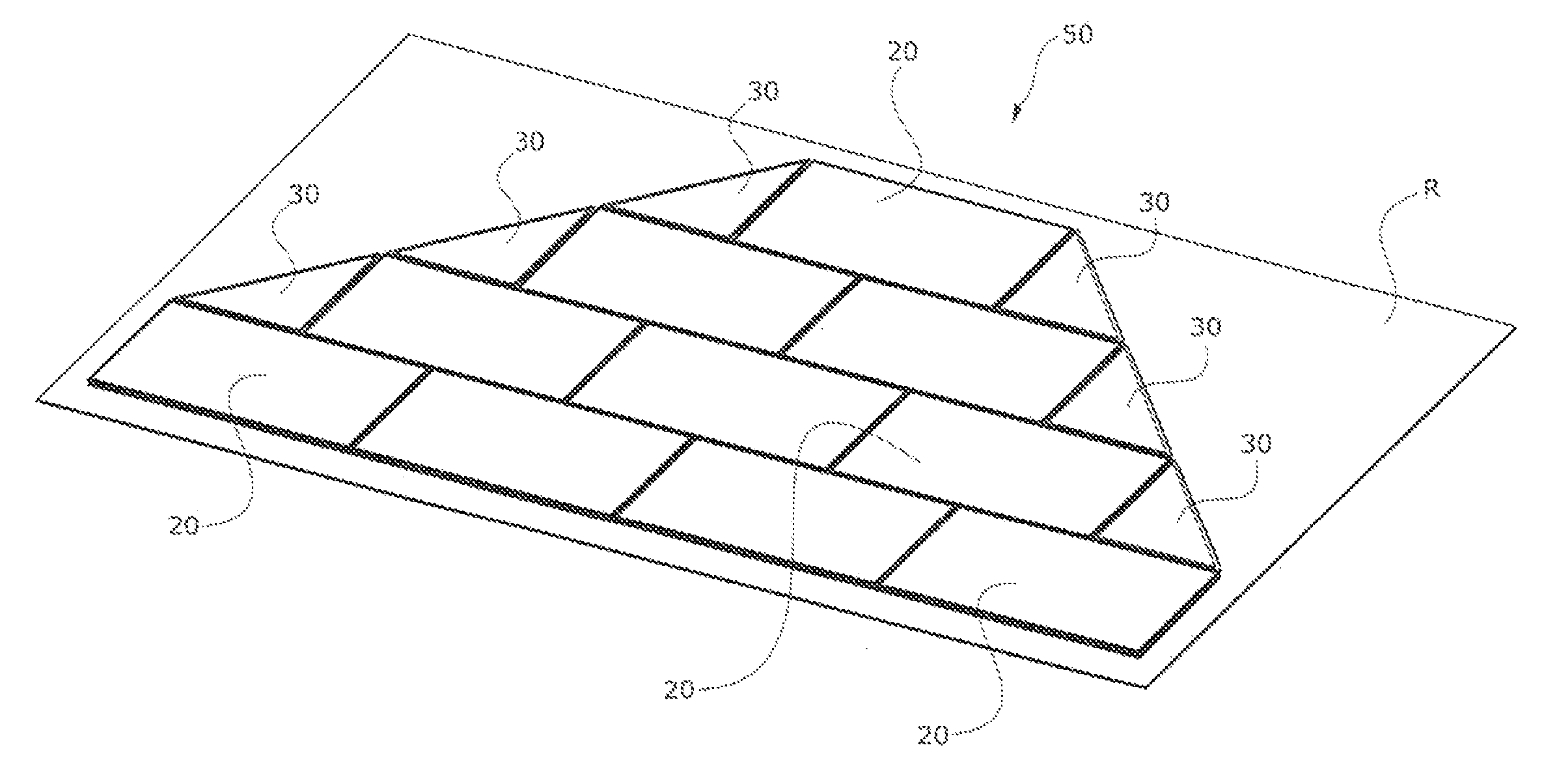
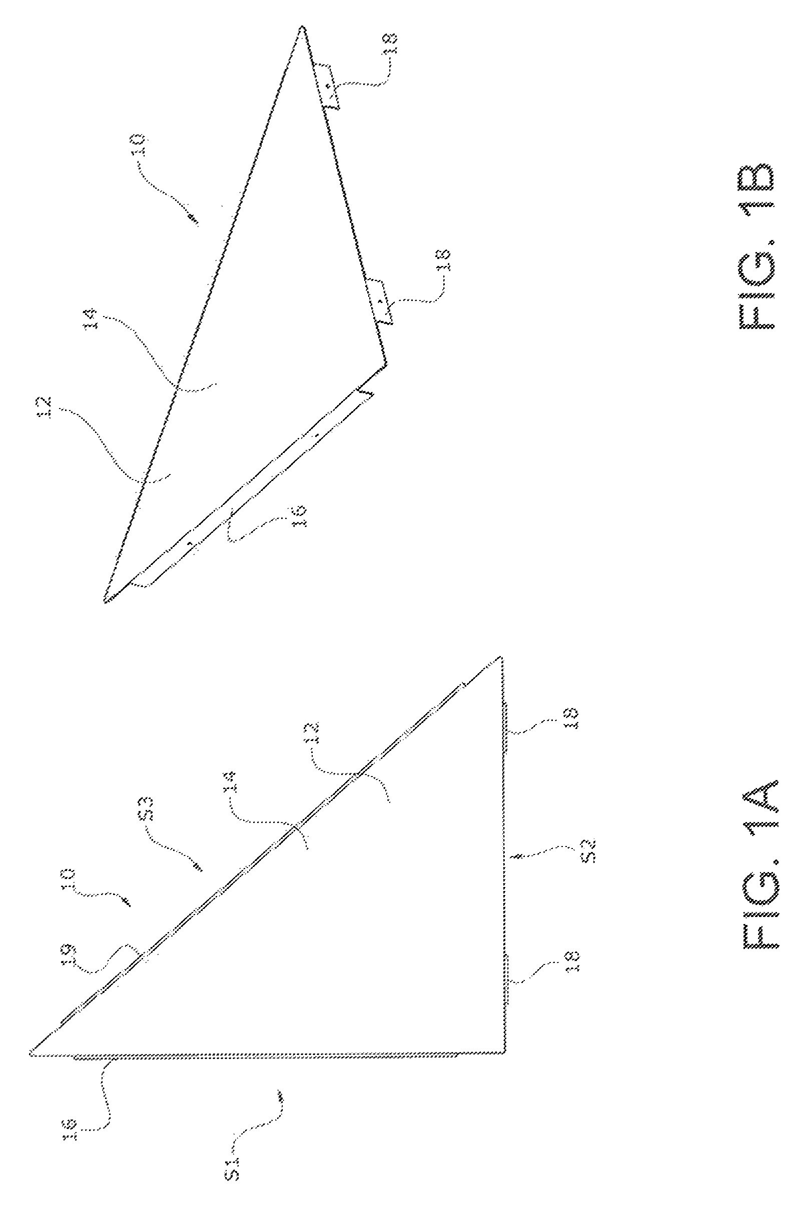
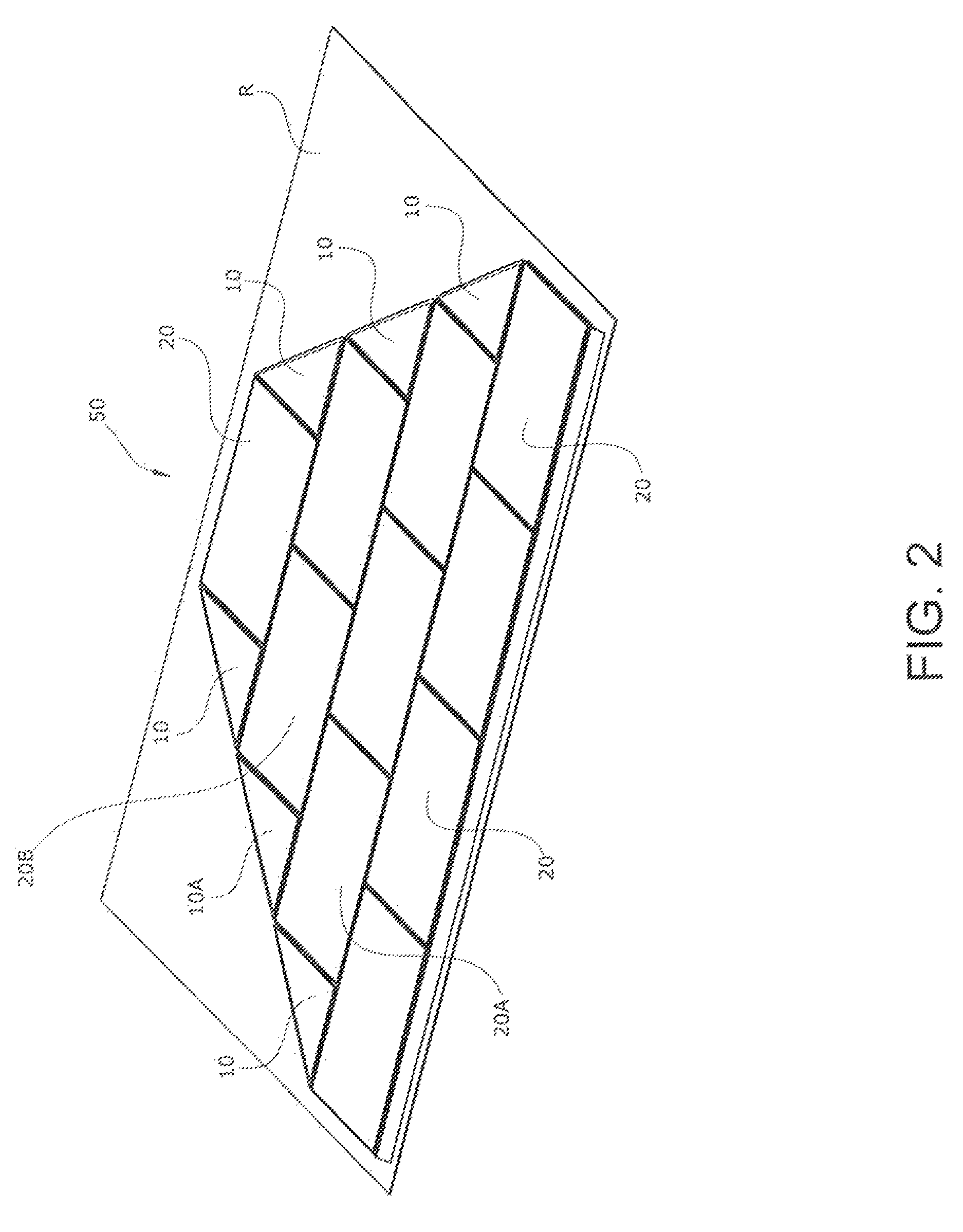
[0032]The present invention provides an imitation solar module that does not generate electricity itself. It is instead positioned within an array of standard electricity generating solar modules for both structural and aesthetic purposes. This imitation solar module may have a triangular or non-standard shape. A visual representation such as a decal (or other “picture” such as a printed image) of an actual solar module surface is displayed thereon. From an aesthetic point of view, the module has a surface that appears just like a functional solar module such that an observer on the ground will believe the present module generates its own electricity just like the surrounding modules. Simply put, the imitation module will look just like one of the electricity generating modules in the array. A passer by will not notice that the module in question is merely an imitation meant to look like the adjacent fully functioning modules.
[0033]The main body portion of the present imitation module is preferably a thin panel of sheet metal. Being thin and easy to cut and work with, another aesthetic benefit is that the present module can be cut in a variety of novel shapes such that it can be used to fit at the edges of the array, or even around or beside obstructions in the center of the array. From a structural point of view, however, the imitation module has side flanges with connectors thereon to provide both grounding and load sharing with the adjacent (fully functional electricity generating) modules.
[0034]FIGS. 1a to 2 show a first triangular embodiment of the invention. FIGS. 3A to 4 show a second truncated triangular embodiment of the invention. FIGS. 5 to 8B show a module-to-module coupling system for use with the present system. Lastly, FIGS. 9A through 13 show arrays with a variety of novel-shaped imitation solar modules for use in fitting around various roofing obstructions.
[0035]Referring first to FIGS. 1A to 3, triangular-shaped solar module 10 is seen. Solar module 10 generates no power of its own. Instead, as seen in FIG. 2, modules 10 are used to round out or fill the corners of an array 50 on the top of a building's roof R. In array 50, triangular-shaped modules 10 do not generate electricity. Instead, only standard photovoltaic modules 20 generate electricity.
[0036]As can be seen, triangular-shaped modules 10 offer aesthetic benefits in that they provide a much more appealing shape for the overall array 50. Specifically, the array 50 does not have the all too common appearance of a staggered module solar array which looks like bricks in an unfinished wall.
[0037]It is to be understood, however, that triangular-shaped modules 10 may add other structural, electrical and non-aesthetic benefits to the array design. For example, modules 10 provide electrical grounding between adjacent photovoltaic modules 20. Moreover, modules 10 provide load balancing and distribution between the adjacent photovoltaic modules 20.
[0038]As will be shown, triangular-shaped modules 10 advantageously need only be connected to adjacent (electricity-generating) modules 20 on two sides. Since the two sides of module 10 which are connected to modules 20 are the shorter sides (leaving only the hypotenuse unconnected to an adjacent module), modules 10 are slightly cantilevered in position. However, due to their triangular shape (and thin body structure), the cantilever effect is minimized. Thus, connections to adjacent modules 20 on only two of the three sides of module 10 are all that is required to support it in position.
[0039]In preferred aspects, the present system provides an imitation solar module for use in a photovoltaic array, comprising: a flat triangular shaped body portion 12 with a visual representation 14 of a portion of a photovoltaic module displayed on the flat triangular shaped body portion. In one aspect, visual representation 14 is simply a decal or printed or otherwise attached “picture” of a triangular section of an actual electricity-generating photovoltaic module. Basically, module 10 is simply made to look like a fully functioning photovoltaic module. When viewed from the ground, the array 50 will look like a creatively designed and shaped photovoltaic module array. An observer on the ground will not know that only modules 20 generate power while modules 10 simply look like fully functioning electricity-generating modules.
[0040]In optional preferred aspects, the decal (or printed picture) that comprises the visual representation 14 is designed such that it looks exactly like a series of standard photovoltaic cells on the surface of the adjacent electricity generating solar modules. In one exemplary embodiment, the decal comprises a substrate made of (PVC free) Envision Print Wrap™ Film or Controltac™ Graphic Film made by 3M of Saint Paul, Minn. with a covering laminate made of or Scotchcal™ Lustre Overlaminate also made by 3M. However, other suitable materials can also be used, all keeping within the scope of the present invention. Preferably, the decal or image is made or printed with a material that is both UV resistant and fade resistant. The image will have the same color as the surface of the neighboring electricity generating modules. Ideally, the module glare, reflectivity, and even the visual images of the traces (e.g.: the bus bars and metallization grid lines of the cells) will be made to match or be the same as those of the fully functioning modules. Thus, the visual image will match the cell spacing, color, and even texture of a working electricity generating module as closely as possible. Even the backsheet color is preferably chosen to match that of the electricity generating modules. When designed, the image is preferably sufficiently detailed such that it has the randomized cell colors and color gradients typically found on a solar module. (Normally, some cells are slightly darker and some are slightly lighter than one another, or some are slightly greener while others appear more purple than one another). Ideally, the visual representation 14 is designed to mimic these subtle changes. Simply put, it will look like the crystalline structure of a fully functioning solar cell module.
[0041]As stated above, triangular-shaped module 10 has a thin, planar, flat triangular shaped body portion 12. Body portion 12 is optionally given structural rigidity by a first side flange (or flanges) 16 extending downwardly from a first side 51 of the triangular shaped body portion. In addition, a second side flange (or flanges) 18 extends downwardly from a second side S2 of the triangular shaped body portion. Lastly, a third side flange (or flanges) 19 may extend downwardly from the third side S3 of the triangular shaped body portion.
[0042]As illustrated in FIG. 1, sides S1 and S2 may be the roughly same length (thereby giving the corners of body portion two roughly 45 degree angles. Note: in the actual illustration, one angle is approximately 40 degrees whereas the other is approximately 50 degrees. It is to be understood that the present triangle-shaped design encompasses any range of preferred angles (for example from 20 to 70 degrees). The longer (hypotenuse) side S3 may preferably be opposite to the 90 degree angle of the triangle.
[0043]As seen in FIG. 2, an exemplary imitation module 10A may be connected to a first adjacent photovoltaic module 20A which is adjacent in a Y-direction and to a second adjacent photovoltaic module 20B which is adjacent in an X-direction.
[0044]FIGS. 3A to 4 illustrated a second (truncated-triangle) embodiment of the imitation solar module. In this embodiment, solar module 30 has a side groove 32 extending therearound. Groove 32 is dimensioned to receive any of a variety of coupling elements therein which can be used to connect the sides of imitation module 30 to adjacent fully functioning electricity generating modules 20. FIG. 4 shows six imitation modules 30 together with standard modules 20 forming an aesthetically pleasing shaped array 50.
[0045]In preferred embodiments, modules 10 and 30 may be made of sheet metal, which gives them excellent structural strength to assist with load balancing between the adjacent modules in the array 50, yet is still thin and easy to handle.
[0046]In optional aspects of all the embodiments described herein, further features of how the decal or printed image 14 can be made can be used to enhance the illusion that the present imitation module is fully functioning. For example, decal 14 can be positioned with one of its edges spaced farther from one of the side edges of the triangle shaped body. As a result, when viewed from the ground at a certain angle, the position of decal 14 will give the illusion that a side edge of the triangle (from which the edge of the decal is spaced apart) is a raised frame on the side of the imitation module. Preferably as well, the imitation module is designed such that it appears that the visual representation 14 is at the optimal height such that it appears that it is in the same plane as the rest of the electricity generating solar cells in fully functioning modules 20. This is a unique advantage of the invention in that its main body portion may be made from a thin, planar section of sheet metal, yet still give the illusion that it has the same thickness as the surrounding electricity generating modules. Stated another way, the visual representation 14 can be positioned in the same plane as the cells in the surrounding functioning modules, with the side frames 16 and18 reaching downward from body 12 to provide a platform for couplings which link it to adjacent modules.
[0047]Next, FIGS. 5 to 8B illustrate exemplary systems for connecting module 10 to adjacent modules 20. As seen in FIGS. 5 and 6, a pair of couplings 60 may be placed on two of the sides of the triangle. Coupling 60 may have a generally round base 62 and a T-shaped head 64. Coupling 60 may be received through a hole in side flanges 16 or 18. It may optionally be riveted in place, (such that it rotates but does not over-tighten), but it is to be understood that the present invention encompasses all suitable fastening mechanisms. Note as well that flanges 16 and 18 may either extend partially or fully along the respective sides of module 10. It is to be understood that the present invention encompasses embodiments with one or more flanges on any of its sides.
[0048]In operation, couplings 60 are simply rotated by approximately 90 degrees to lock T-shaped head 64 into a side groove of the first and second adjacent photovoltaic modules. Specifically, FIG. 8A shows couplings 60 with their T-shaped heads 64 rotated to an unlocked position (such that it can be inserted into a side groove in an adjacent module 20) whereas FIG. 8B shows couplings 60 with their T-shaped heads 64 rotated to a locked position (such that it can be securely held within a side groove in an adjacent module 20).
[0049]It is to be understood, that the present invention also encompasses imitation solar modules that do not have a triangular shape. Examples of such non-triangular modules are seen in FIGS. 9A to 13, as follows.
[0050]In FIGS. 9A and 9B, a first imitation module 100 has a circular center hole 102 cut therein such that it can be received around a roof vent V. A second imitation module 110 has a rectangular center hole 112 cut therein so as not to obstruct the view through a skylight SL therethrough. As can be appreciated, one advantage of imitation modules 100 and 110 is how close they can be built to the sides of the roof obstruction. This provides a structurally solid array on the roof, without having to leave any large gaps which a standard rectangular-shaped module does not fit in the remaining spaces. Again, cutting such sections out of the body portion of the imitation module is facilitated by the use of a thin sheet metal panel as the main body portion 12.
[0051]FIG. 10 shows a different situation where two rows of modules 20 are positioned an irregular distance apart. In this situation, a row of imitation modules 120 can be positioned therebetween to act as “spacers”. This situation may occur when one row of modules 20 has to be positioned adjacent to a roof edge, or other obstruction. Modules 120 permit a single array 50 to be formed (as opposed to two separated rows formed of modules 20).
[0052]FIG. 11 shows the situation of two small narrow rectangular imitation modules 130A and 130B partially filling a gap between adjacent electricity generating modules 20. The space between modules 130A and 130B is left open to accommodate an obstruction in the roof (not shown).
[0053]FIG. 12 shows an imitation solar module 140 having a cut out side section that enables the array to be positioned up close against a roof vent V.
[0054]Lastly, FIG. 13 shows four imitation modules 150 (surrounded by fully functioning electricity generating modules 20), where each of imitation modules 150 have a rounded corner section cut out such that they can be arranged as shown to provide space for a roof obstruction (such as a vent or chimney).
[0055]As can be appreciated, the present imitation solar module can be provided in many shapes and sizes. Without limitation, it may be triangular, rectangular or some other regular or irregular shape. It may have straight edges, curved edges or cut-out edges, or any combination of the above.
[0056]In preferred aspects, the body portion of the imitation module is made of aluminum or galvanized sheet metal. However, in further optional embodiments, the body portion of the imitation module may instead be made of steel, glass, plastic, fiberglass, plastic, or other suitable material. In fact, the body portion of the imitation module may be made from an actual photovoltaic module that is simply cut to shape. Such a cut or sliced through module will no longer generate any electricity, but it may be cut into a shape such that it can fit into a triangular or other irregularly shaped imitation module. There are two benefits to cutting up and using existing (but no longer electricity generating) modules in this way. First, their color and visual appearance will be the same as a functioning module, and will not change over time. Second, using old previously functioning modules in new imitation modules provides a system for recycling existing modules that had stopped functioning. Therefore, such old, non-functioning modules can be cut into new shapes (such as triangles) put to use as imitation modules.

PUM

no PUM

Description & Claims & Application Information

We can also present the details of the Description, Claims and Application information to help users get a comprehensive understanding of the technical details of the patent, such as background art, summary of invention, brief description of drawings, description of embodiments, and other original content. On the other hand, users can also determine the specific scope of protection of the technology through the list of claims; as well as understand the changes in the life cycle of the technology with the presentation of the patent timeline. Login to view more.

Similar technology patents

Integrated battery unit for electric vehicles

ActiveUS20070090810A1easily instal
Owner:WEBASTO CHARGING SYST INC

Removable fletching for use with archery arrows

InactiveUS20060258491A1easily instal
Owner:WALSH TIMOTHY C

Refrigerator and control method thereof

InactiveUS20130042641A1easily instalfrost forming at be prevent
Owner:SAMSUNG ELECTRONICS CO LTD

Classification and recommendation of technical efficacy words

  • inexpensive to manufacture
  • easily instal

Disposable transducer seal

ActiveUS20050154313A1inexpensive to manufacturequickly and easily instal
Owner:SOLTA MEDICAL

Low cost safety lancet

ActiveUS20070185515A1inexpensive to manufactureeasily assemble together
Owner:FACET TECH LLC

Passive Entry System for Automotive Vehicle Doors

ActiveUS20090160211A1durable in constructioninexpensive to manufacture
Owner:FORD GLOBAL TECH LLC

Fiber optic cables and assemblies for fiber toward the subscriber applications

ActiveUS20110229098A1small cross sectioninexpensive to manufacture
Owner:CORNING OPTICAL COMM LLC

Robot System

ActiveUS20100145520A1easily instalsimple to use
Owner:COMAU SPA

Embodiments of Lateral Displacement Shock Absorbing Technology and Applications Thereof

InactiveUS20100258988A1easily instalfacilitate alignment
Owner:BAUER PERFORMANCE LACROSSE

Dynamic Vehicle Display System

InactiveUS20080211652A1easily instaleasily couple
Owner:NANOLUMENS ACQUISITION
Why Eureka
Try Eureka