Lavatory system

a technology of lavatory system and lava chamber, which is applied in the direction of water installation, washstand, construction, etc., to achieve the effect of preventing the activation of the soap dispenser

Active Publication Date: 2015-02-10
BRADLEY FIXTURES CORP
View PDF862 Cites 30 Cited by
  • Summary
  • Abstract
  • Description
  • Claims
  • Application Information

AI Technical Summary

Problems solved by technology

However, such known lavatory systems typically require multiple custom designed and manufactured components, such as multiple lavatory systems for placement at the various heights.

Method used


Image

  • Lavatory system
  • Lavatory system
  • Lavatory system

Examples


Embodiment Construction

[0065]With reference now to the drawing figures in which like reference numerals designate like parts throughout the disclosure.

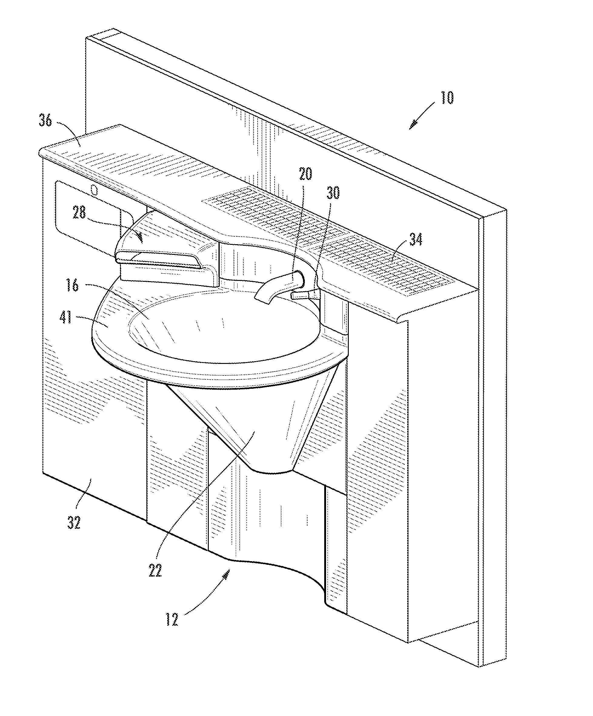
[0066]FIGS. 1 through 12 show a lavatory system 10 according to another exemplary embodiment. The embodiments illustrated in FIGS. 1 through 12 may be configured to be supported by an adjacent wall 11 (as shown) or may be a freestanding structure configured to be supported by a base (e.g., legs, pedestal, vanity, etc.).

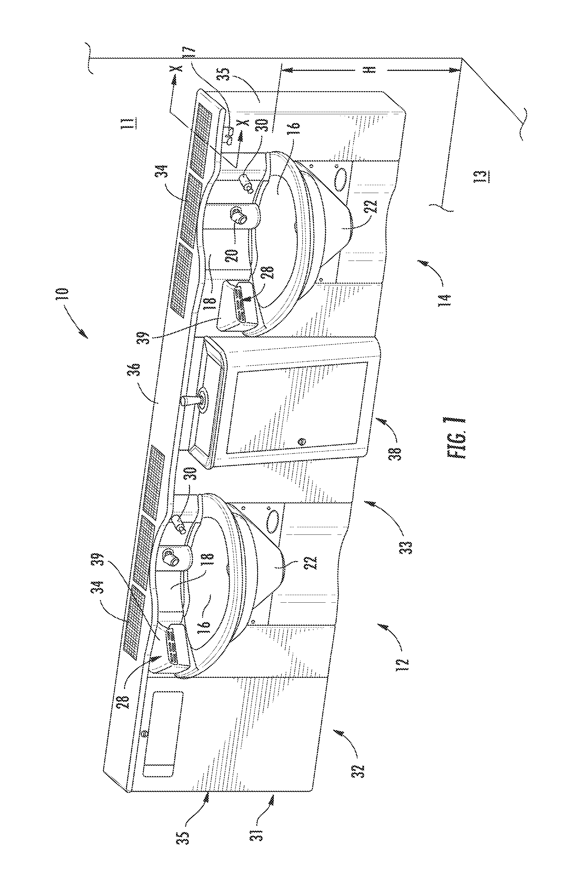
[0067]According to the embodiment illustrated, lavatory system 10 includes two washing stations (e.g., hand washing stations), shown as a first or upper station 12 and a second or lower station 14, mounted to a base (e.g., housing, cabinet, etc.). Alternatively, the lavatory system may include any number of washing stations (e.g., one, three, four, or more) arranged in any of a variety of configurations (e.g., all upper stations, all lower stations, mixed upper / lower stations, etc. set at a variety of upper / lower patterns, heights (“H” in FIG...


PUM


Abstract

A lavatory system is disclosed including one or more integrated hand washing stations. Each hand washing station includes a basin, a faucet, a solenoid valve configured to control water flow to the faucet, and an electric hand dryer located adjacent the basin and the faucet so that the user of the washing station may use the faucet and the electric hand dryer without leaving the washing station. The electric hand dryer preferably includes an outlet to direct air across the associated basin so that any water that drips from the user's hands fall within the basin. A control system may be provided to control activation of the fixtures such as the solenoid valve, the electric hand dryer, and / or soap dispenser. The control system may be configured to inhibit simultaneous activation of the solenoid valve and the hand dryer. A photovoltaic system may be provided to provide power.

Description

CROSS REFERENCE TO RELATED APPLICATIONS[0001]This application claims the benefit of U.S. Provisional Application No. 60 / 994,580, filed Sep. 20, 2007, U.S. Provisional Application No. 61 / 028,852, filed Feb. 14, 2008, U.S. Provisional Application No. 61 / 046,319, filed Apr. 18, 2008, and U.S. NonProvisional patent application Ser. No. 12 / 223,466, filed on Sep. 18, 2008, all four of which are expressly incorporated herein by reference in their entireties.FIELD OF THE INVENTION[0002]The present invention relates to a lavatory system. More particularly, the present invention relates to a lavatory system with hand washing stations that can be positioned at a variety of heights relative to the floor.BACKGROUND OF THE INVENTION[0003]It is known to install a plurality of fixtures in a public, commercial or industrial, residential or non-residential environment such as a restroom. Such known fixtures include a lavatory system, towel dispensers, waste receptacles, hand-dryers, and the like. Lav...

Claims


Application Information

Patent Timeline
Patent Type & Authority Patents(United States)
IPC IPC(8): E03C1/05A47K5/12E03C1/01
CPCE03C1/057E03C1/01A47K2005/1218E03C1/322
Inventor LOBERGER, JOHN M.RENNER, JASON M.JAWORSKI, JEFFERY S.THIELKE, MARK A.MEYER, MARK A.KOHLWEY, KEVIN M.CARPIAUX, DOUGLASDE LAY, DANIEL J.WALTERS, GLENN T.WALTERS, RICHARDHAUSER, II, JON W.
Owner BRADLEY FIXTURES CORP
Why Eureka
Try Eureka