Evaporative condenser cooling unit and method

a cooling unit and condenser technology, applied in the field of air conditioner systems and methods, can solve problems such as eccu being disabled, achieve the effects of reducing utility bills, reducing peak demand on utility companies, and reducing end user's utility bills

Inactive Publication Date: 2015-02-10
PHOENIX MFG
View PDF28 Cites 4 Cited by
  • Summary
  • Abstract
  • Description
  • Claims
  • Application Information

AI Technical Summary

Benefits of technology

[0009]A main objective for using the evaporative condenser cooling unit on an air conditioner is so that the air condition system consumes less electricity and reduces the peak demand on utility companies as well as reduces end user's utility bills. In one example, an air conditioner system that has the evaporative condenser cooling unit reduces electrical usage by up to 25% compared to the air condition system without the evaporative condenser cooling system and reduces peak loading to the utility companies by up to 2 KWH per household. This energy savings is accomplished by the ECCU supplying cool air to the condenser unit, permitting it to operate in its peak efficiency temperature range.
[0010]To further enhance the efficiency of the ECCU, several controls are provided to limit the use of the ECCU when the outside temperature is moderate and when the condenser unit will operate efficiently without needing the ECCU. In addition, when the outside temperature is low enough for the condenser unit to switch into heat pump mode, the ECCU is disabled.
[0011]The Evaporative Cooled Condenser Unit employs a quiet motor / fan system that pulls air across an evaporative media pad, through a drift eliminator, and delivers cool air to a condensing unit thereby increasing the operating efficiency of the air conditioner via a condenser enclosure that is adjustable for various sizes of condenser units and that includes a plurality of barometric dampers to provide failsafe operation and provide for air flow to the condenser during heat pump operation without the motor of the ECCU operating.

Problems solved by technology

In addition, when the outside temperature is low enough for the condenser unit to switch into heat pump mode, the ECCU is disabled.

Method used


Image

  • Evaporative condenser cooling unit and method
  • Evaporative condenser cooling unit and method
  • Evaporative condenser cooling unit and method

Examples


Embodiment Construction

[0024]For the purpose of promoting an understanding of the principles of the invention, reference will now be made to the embodiments illustrated in the drawings and specific language will be used to describe the same. It will nevertheless be understood that no limitation of the scope of the invention is thereby intended, such alterations and further modifications in the illustrated device, and such further applications of the principles of the invention as illustrated therein being contemplated as would normally occur to one skilled in the art to which the invention relates.

[0025]The drawings include descriptive text and examples identifying components for preferred embodiments, which are incorporated herein by reference.

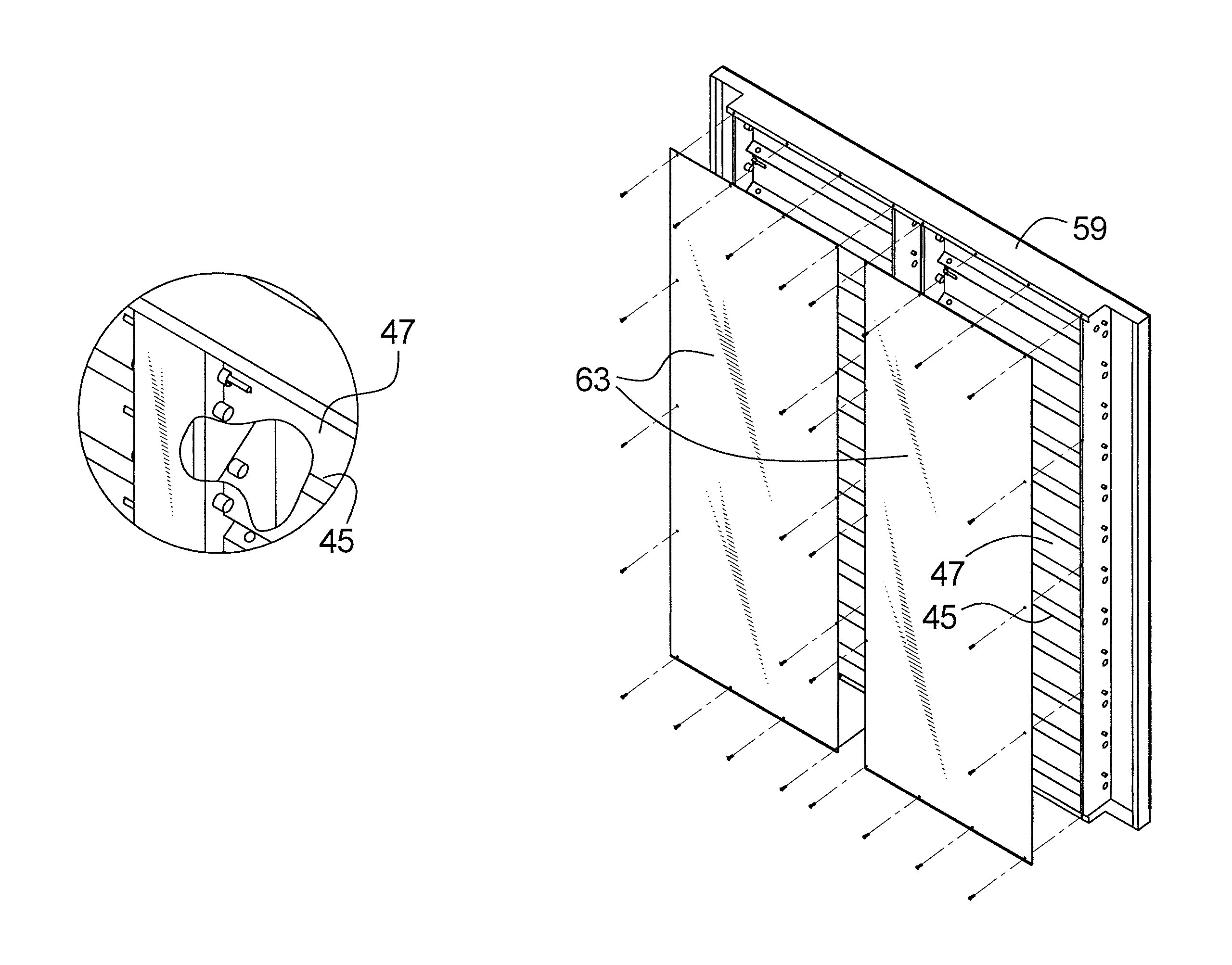
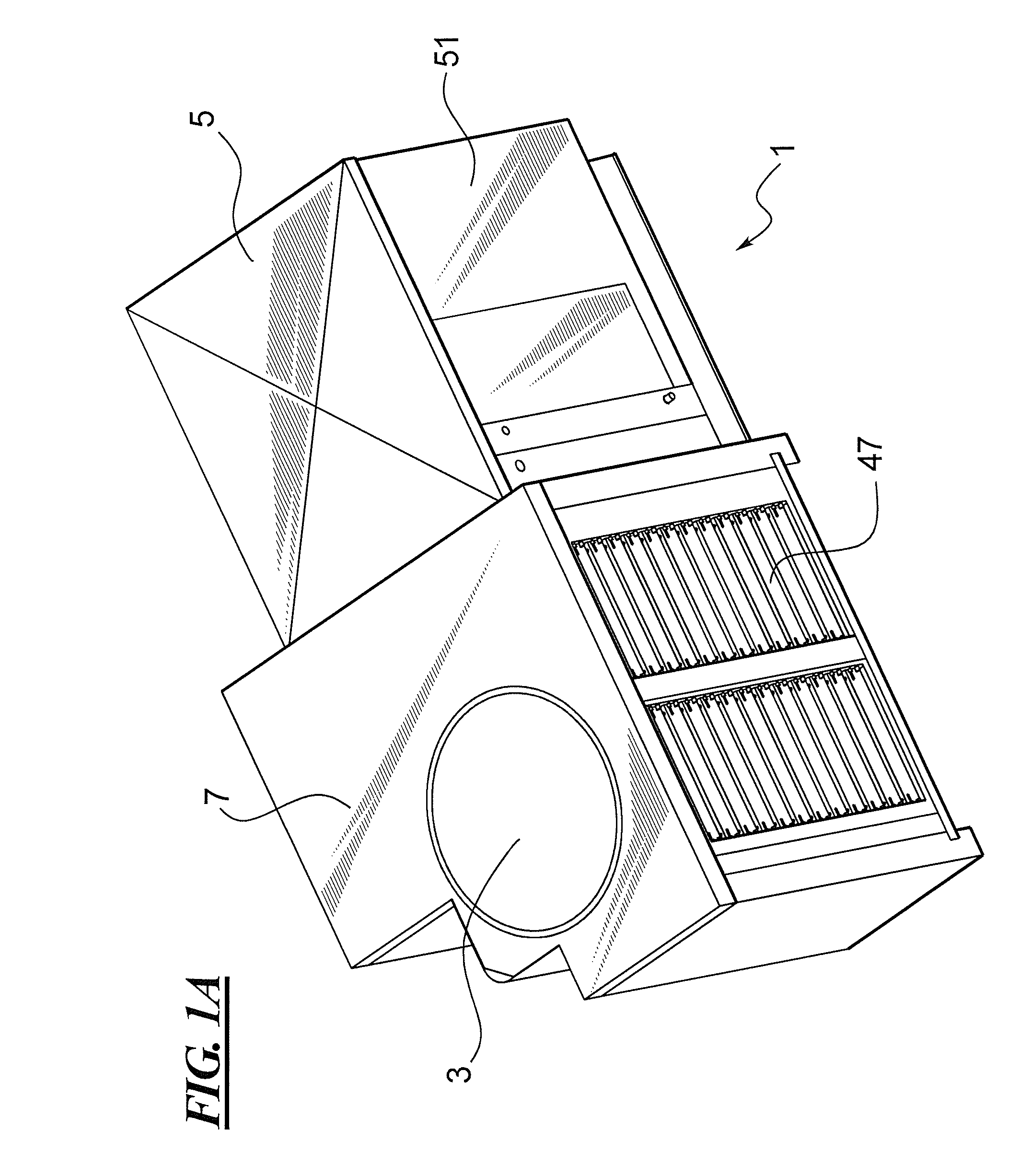
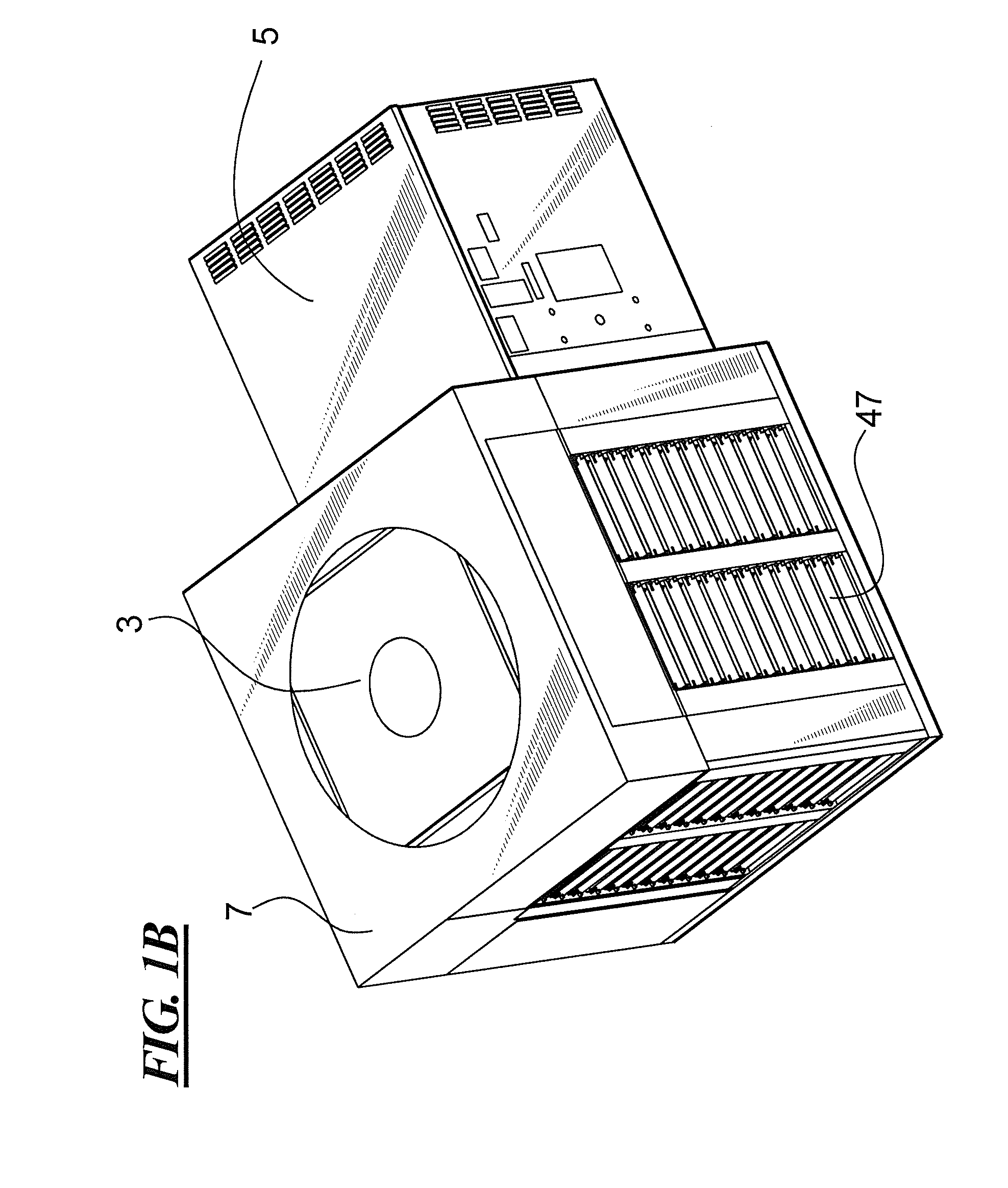
[0026]Referring to FIGS. 1A and 1B, there is illustrated a typical application of the evaporative condenser cooling unit, or ECCU 1, with a typical condenser unit 3 of an air conditioner system. Since the focus of the present invention is directed to the ECCU 1 and...


PUM


Abstract

An evaporative cooled condenser unit employs a quiet motor / fan system that pulls air across an evaporative media pad, through a drift eliminator and delivers cool air to a condensing unit of an air conditioner thereby increasing the operating efficiency of the air conditioner. A condenser enclosure into which the cool air is delivered is adjustable for various sizes of condenser units and contains a plurality of barometric dampers to provide failsafe operation and provide for external air flow to the condenser during heat pump operation or when the auxiliary cooling module is disabled.

Description

CROSS-REFERENCE TO RELATED APPLICATION[0001]This application claims priority to U.S. Provisional Application Ser. No. 61 / 526,550 filed Aug. 23, 2011, the entire disclosure of which is hereby incorporated by reference herein.BACKGROUND OF THE INVENTION[0002]1. Field of the Invention[0003]The present invention relates generally to an air conditioner system and method, and more particularly to a system and method that includes an air cooler to provide cooled air to a condenser of an air conditioner system.[0004]2. Description of the Related Art[0005]Air conditioner systems for cooling interior spaces such as interiors of homes, offices, stores, or other buildings that use a forced air HVAC system operate by cycling the air conditioner on and off to regulate the interior temperature to the desired level. When the air conditioner is on, it draws power. The more time that the air conditioner is on during the cycle, the greater the amount of power required to operate the air conditioner. A...

Claims


Application Information

Patent Timeline
Patent Type & Authority Patents(United States)
IPC IPC(8): F25D17/06F24F1/14F24F1/42F24F5/00F25B39/04F28B5/00F28B11/00F28D5/00
CPCF25B39/04F28B5/00F28B11/00F24F1/14F24F5/0035F28D5/00F25B2339/041F24F1/42Y02B30/545F28F2275/085Y02B30/54
Inventor TOWNSEND, DONALD I.CHAVEZ, LAWRENCE R.JOUAS, GARY STEPHEN
Owner PHOENIX MFG
Why Eureka
Try Eureka