
Manifold system for gas and fluid delivery

a fluid flow control and filtering device technology, applied in valve housings, process and machine control, instruments, etc., can solve the problems of high material cost, high additional manufacturing cost of individual operative fluid flow control and filtering devices, and the need for costly seals otherwise needed, so as to achieve low cost, reduce manufacturing costs, and reduce the effect of machining

Inactive Publication Date: 2015-02-10
ADVANTAGE GROUP INT
View PDF74 Cites 16 Cited by
  • Summary
  • Abstract
  • Description
  • Claims
  • Application Information

AI Technical Summary

Benefits of technology

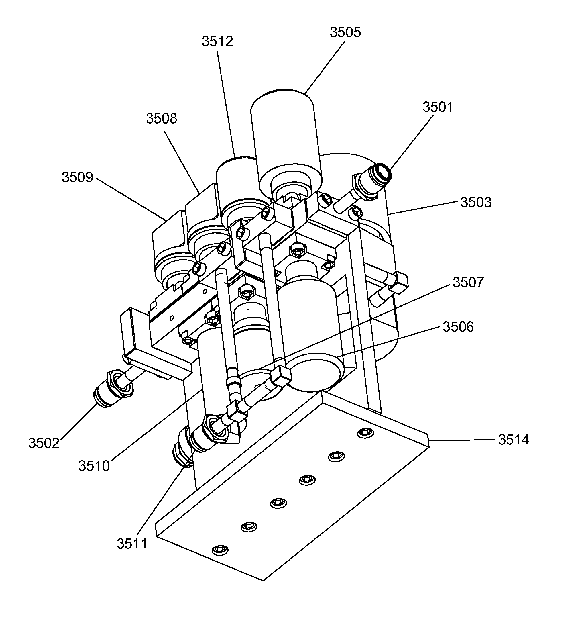
[0019]The present disclosure also enables the placement of operative fluid flow control and pressure sensing devices on the front and back sides with the minimal use of difficult to obtain ultrapure stainless steel, minimal machining, minimal part count, and extremely compact size without the need for additional pipe fitting, welding, and plumbing activities, which require special skills and which generate expensive down time. Although prior art modular surface mount designs required that all operative fluid flow control and filtering devices be located on the same side of the individual gas sticks for ease of maintenance, actual experience shows that gas sticks for toxic and inert gasses do not require this access since the operative fluid flow control and filtering devices that form these gas sticks have very high reliability and rarely need to be replaced. Experience also shows that when a gas stick used on a corrosive gas fails, the entire stick is removed as an assembly by the end user instead of their independently replacing individual devices.

Problems solved by technology

The welding of the standardized blocks obviates costly seals otherwise needed to prevent leakage.
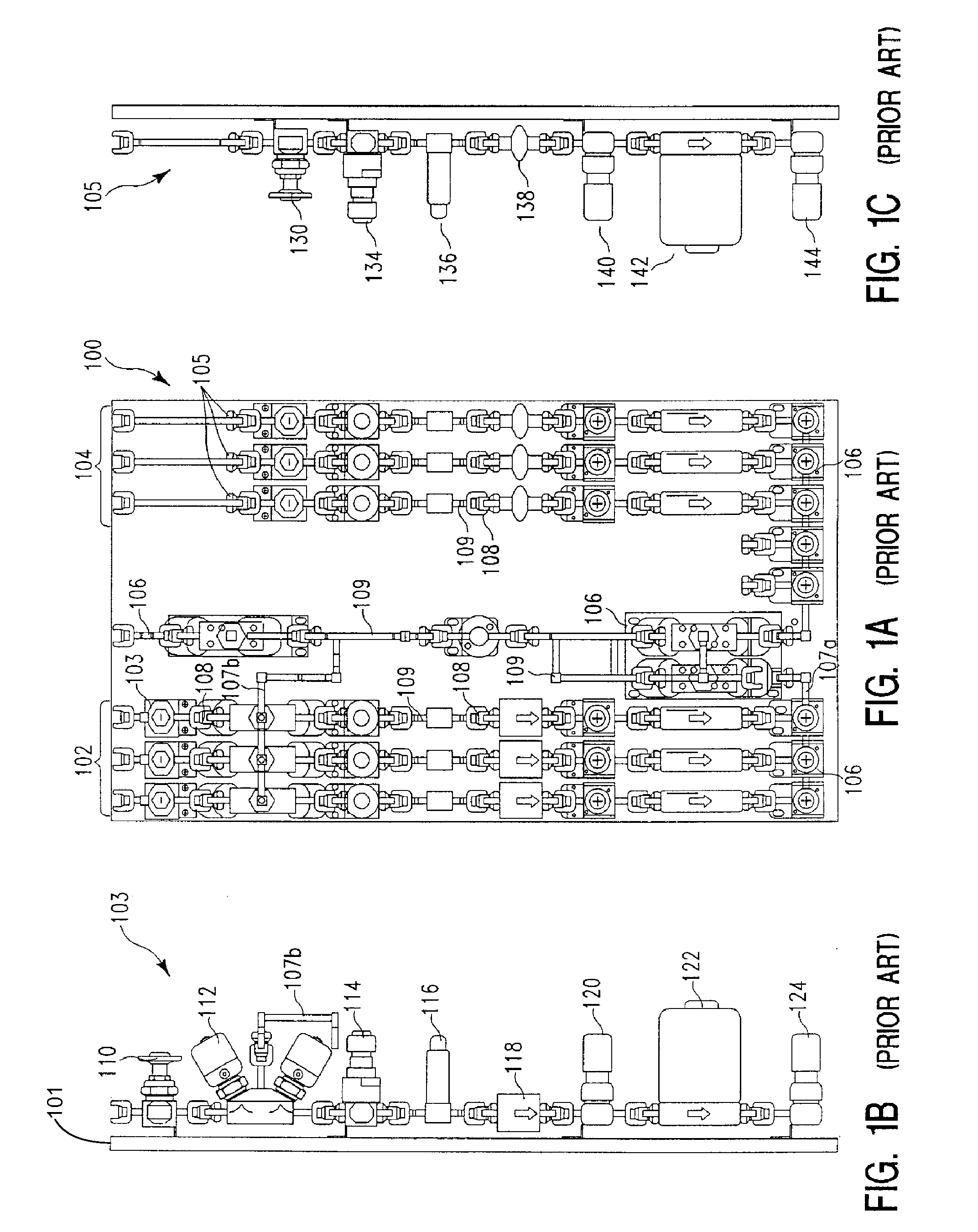
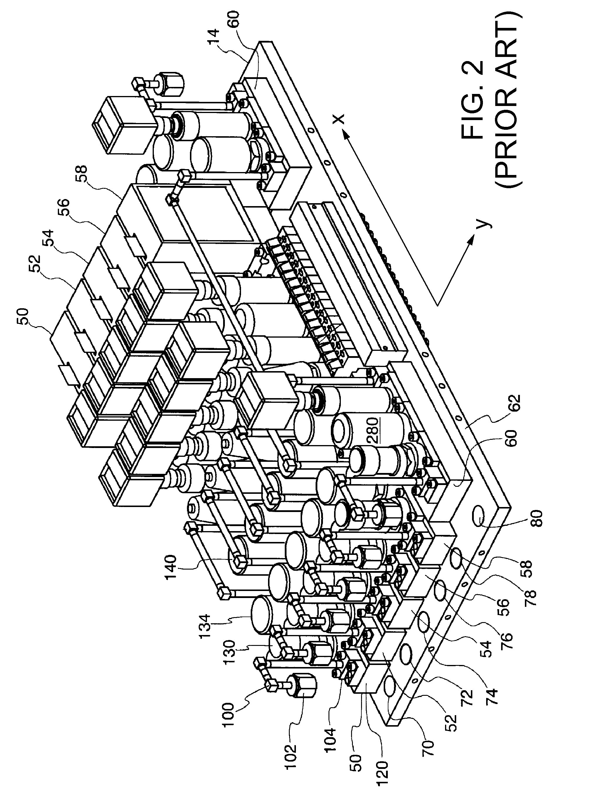
Those skilled in the art recognize a number of issues associated with prior art fluid distribution systems.
First, cost of materials is quite high due to the extensive amount of difficult to obtain and costly ultra-pure stainless steel involved in the manufacture of individual operative fluid flow control and filtering devices that make up a gas stick.
Additional manufacturing costs for individual operative fluid flow control and filtering devices are quite high due to multiple machining steps and the multiple fittings and pipe sections that need to be welded so that the individual operative fluid flow control and filtering devices can be secured to one another.
Similarly the assembly and disassembly of those devices can be relatively labor intensive.
This type of design is also prone to leakage due to the loosening of fittings under sustained vibration loads.
Nevertheless, modular surface mount designs continue to incorporate a relatively significant amount of costly ultra-pure stainless steel.
Modular surface mount designs also require an inordinate number of parts to complete a gas delivery system.
High part count results in significant inventory control problems and possible parts shortages.
Also, large number of parts increases the complexity of manufacturing.
This requirement drives costly and more complex designs for gas sticks.

Method used


Image

  • Manifold system for gas and fluid delivery
  • Manifold system for gas and fluid delivery
  • Manifold system for gas and fluid delivery

Examples


first embodiment

[0082]FIG. 7A is a top view first embodiment of the present invention fluid delivery system showing a plurality of process gas channels incorporated into a common manifold plate. The system can incorporate one or more process gas channels. These channels do not have to be identical. For the purpose of demonstration, the system described includes five parallel flow channels that are substantially identical. Mass flow controllers are used to bridge the gas channels and the common lower manifold to form an operative fluid control system. FIG. 7A shows the embodiment of a first fluid delivery system 700 having a plurality of process gas channels 701, 702, 703, 704, and 705 incorporated into a single manifold plate, and a common lower manifold 706. In this instance the process gas channels 701, 702, 703, 704, and 705 are substantially identical. Each channel includes an inlet 707 as is shown in the exemplary channel 705. The common lower manifold 706 also includes an end wall or face 708...

second embodiment

[0086]FIG. 9A is a top view second embodiment of the present invention fluid delivery system showing a plurality of process gas channels incorporated into a common manifold plate. The system can incorporate one or more process gas channels. These channels do not have to be identical. For the purpose of demonstration, the system described includes five parallel flow channels that are substantially identical. Mass flow controllers are used to bridge the gas channels and the common lower manifold to form an operative fluid control system. FIG. 9A shows a second fluid delivery system 900 having a plurality of process gas channels 901, 902, 903, 904, 905 incorporated into a single manifold plate, and a common lower manifold 906. In this instance the process gas channels 901, 902, 903, 904, and 905 are substantially identical. Each channel includes an inlet 907 as is shown in the exemplary channel 905. The common lower manifold 906 also includes an end wall or face 908 and a common outlet...

third embodiment

[0089]FIG. 11A shows a top view third embodiment of the present invention fluid delivery system showing a plurality of process gas channels incorporated into a common manifold plate. The system can incorporate one or more process gas channels. These channels do not have to be identical. For the purpose of demonstration, the system described includes five parallel flow channels that are substantially identical. Mass flow controllers are used to bridge the gas channels and the common lower manifold to form an operative fluid control system. FIG. 11A shows a third fluid control system 1100 having a plurality of process gas channels 1101, 1102, 1103, 1104, 1105 incorporated into a single manifold plate, and a common lower manifold 1106. In this instance the process gas channels 1101, 1102, 1103, 1104, and 1105 are substantially identical. Each of the channels includes an inlet 1107 as is shown in the exemplary channel 1105. The common lower manifold 1106 also includes an end wall or fac...


PUM


Abstract

A fluid delivery system includes a manifold plate having an upper surface, four vertical sides, and a lower surface opposite the upper surface, where the manifold plate includes a gas inlet, a gas outlet, and a plurality of component receiving stations, one or more component receiving stations located on the upper surface and two or more component receiving stations located on the lower surface. The manifold plate also includes a plurality of internal fluid passageways interconnecting the gas inlet, the plurality of component receiving stations, and the gas outlet. The system also includes a plurality of active fluid components, one active fluid component coupled to a corresponding one component receiving station on the manifold plate. The fluid delivery system can be configured having a single channel or a dual channel.

Description

RELATED APPLICATIONS[0001]This application claims priority of U.S. Provisional Application, Ser. No. 61 / 518,184, filed May 2, 2011, and entitled “Two Sided Manifold Body For Gas And Fluid Delivery Systems.” This application also claims priority of U.S. Provisional Application, Ser. No. 61 / 519,582, filed May 25, 2011, and entitled “Two Sided Manifold Plate And Rail System For Gas And Fluid Delivery.” This application claims priority of U.S. Provisional Application, Ser. No. 61 / 629,180, filed Nov. 14, 2011, and entitled “Dual Channel Two Sided Manifold Body For Gas And Fluid Delivery Systems.” This application claims priority of U.S. Provisional Application, Ser. No. 61 / 630,133, filed Dec. 5, 2011, and entitled “Dual Channel Manifold System For Gas And Fluid Delivery Systems.” This application incorporates U.S. provisional application, Ser. Nos. 61 / 518,184, 61 / 519,582, 61 / 629,180, and 61 / 630,133 in their entireties by reference.FIELD OF THE INVENTION[0002]The present invention relates...

Claims


Application Information

Patent Timeline
Patent Type & Authority Patents(United States)
IPC IPC(8): F16K27/00G05D7/00
CPCG05D7/00F17D1/00Y10T137/87249Y10T137/87885
Inventor MANOFSKY, JR., WILLIAM L.REDEMANN, ERIC J.JULIAN, DONALD H.
Owner ADVANTAGE GROUP INT
Learn More