Plug-on neutral load center having a rotating neutral rail retained by a two-piece dielectric barrier

a dielectric barrier and neutral load technology, applied in the direction of substation/switching arrangement casing, non-enclosed substation, substation, etc., can solve the problems of time-consuming and laborious process of assembling the dielectric and conductive pieces of the load center before installing it into the enclosur

Active Publication Date: 2015-02-10
SCHNEIDER ELECTRIC USA INC
View PDF36 Cites 15 Cited by
  • Summary
  • Abstract
  • Description
  • Claims
  • Application Information

AI Technical Summary

Problems solved by technology

Assembling the dielectric and conductive pieces of the load center before installing it into the enclosure is a time-consuming, labor-intensive process.

Method used


Image

  • Plug-on neutral load center having a rotating neutral rail retained by a two-piece dielectric barrier
  • Plug-on neutral load center having a rotating neutral rail retained by a two-piece dielectric barrier
  • Plug-on neutral load center having a rotating neutral rail retained by a two-piece dielectric barrier

Examples


Embodiment Construction

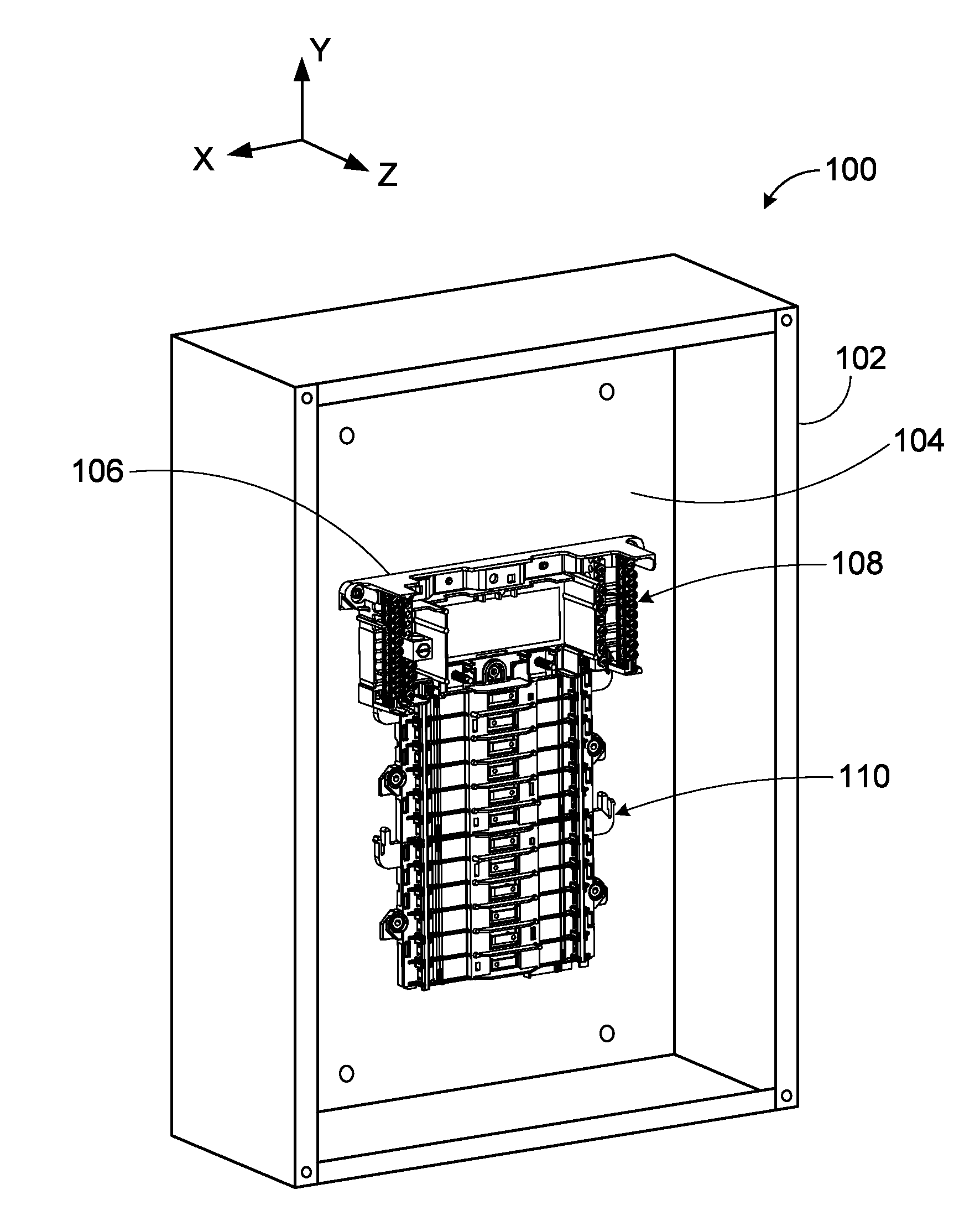
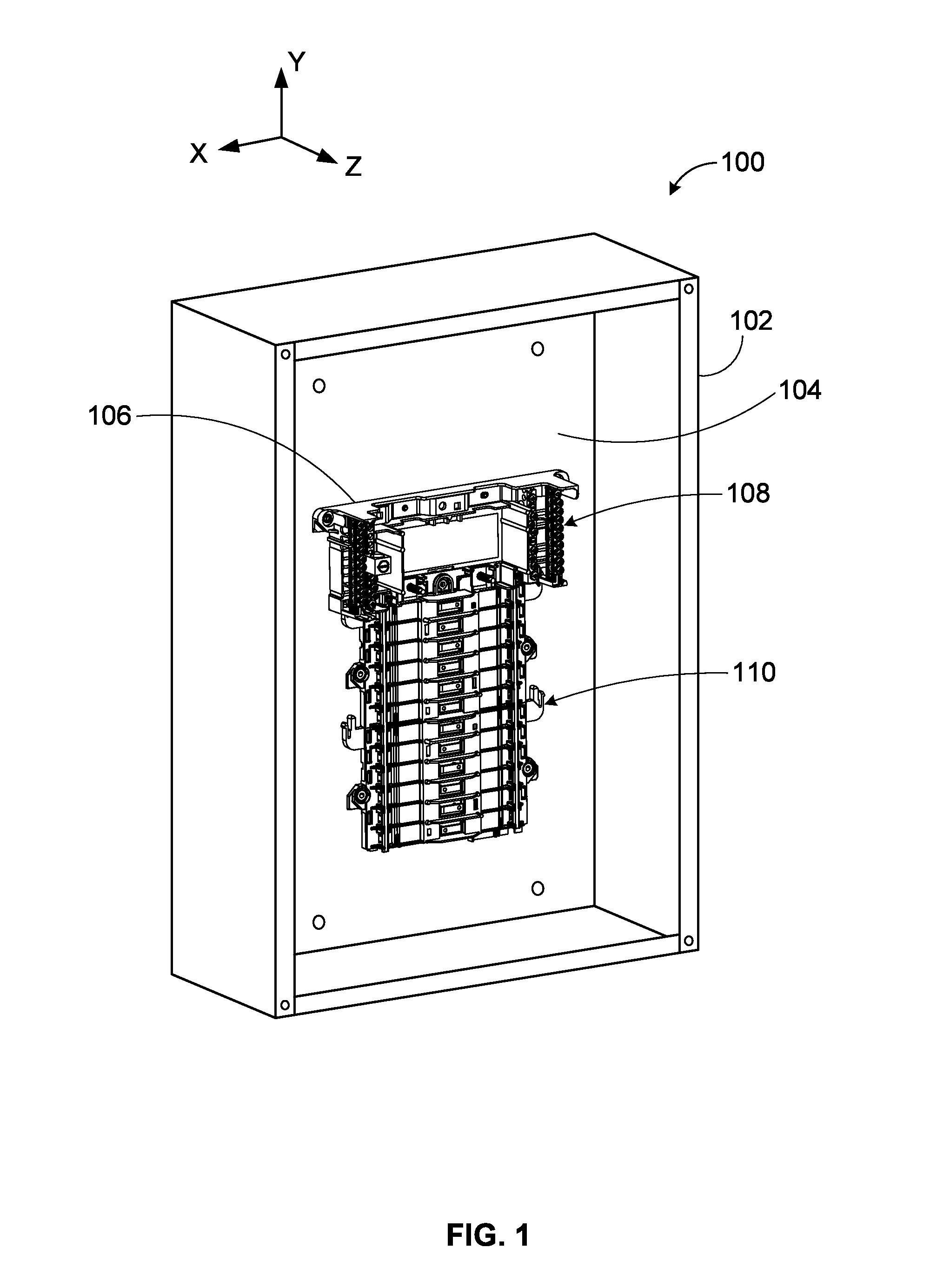
[0036]Referring to FIG. 1, a perspective view of an enclosure 102 of an electrical distribution apparatus 100, such as a panelboard or load center 106, is shown with the door or cover removed so that the lug and mounting connections of the load center 106 to plug-on neutral type circuit breakers can be seen. The load center 106 includes a main section 108 and a plug-on section 110. In general, like reference numbers refer to like structures throughout the figures and various embodiments, and a reference number starts with the number of the figure where the reference number is first introduced. The enclosure 102 is metal and has a rear wall 104 opposite the panel or door (not shown) to which the main section 108 and the plug-on section 110 is mounted.

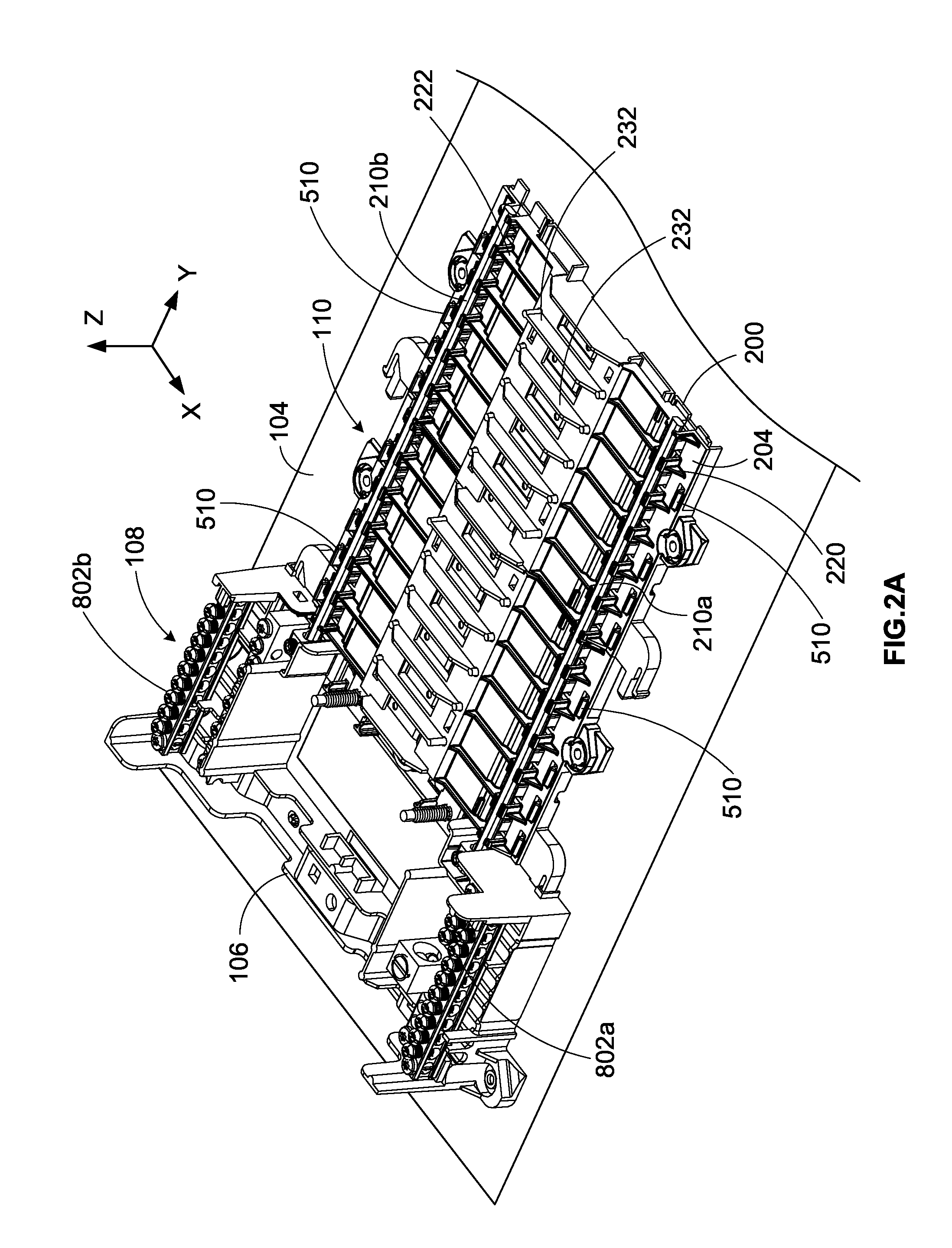
[0037]The focus of this disclosure is on the plug-on section 110, which features a neutral rail 210 (FIG. 2A) as described in more detail below. The neutral rail 210 is made of an electrically conducting material such as aluminum or copp...


PUM

PropertyMeasurementUnit
distance d2aaaaaaaaaa
lengthaaaaaaaaaa
lengthaaaaaaaaaa

Abstract

A load center featuring a two-piece dielectric barrier that securely retains a plug-on neutral rail and methods of assembling the same. The barrier includes a shield and a base having a protrusion that cooperates with fingers of the shield to securely retain the conductor in the load center. The shield is installed over the base and rests on hooks protruding from the base. This creates a distance between the protrusion and the fingers to allow the conductor to be inserted through a gap between the fingers along the conductor's skinny edge. The conductor rotates 90 degrees until it rests on the protrusion. The base and shield are snapped together, causing the hooks of the base to attach to the shield. At the same time, the fingers of the base move downward to rest against the conductor so that it is sandwiched securely between the protrusion and the fingers.

Description

FIELD OF THE INVENTION[0001]The present disclosure relates to electrical distribution equipment and methods of assembling the same, and in particular, to a plug-on neutral load center featuring a neutral rail that is installed in a Z-axis direction and methods of assembling the same.BACKGROUND[0002]A load center is housed within a metal enclosure or panel and holds multiple circuit breakers that are connected to various branch circuits in an electrical distribution system. Some load centers feature a plug-on neutral rail or conductor to which neutral connectors or jaws of the circuit breakers plug onto. These plug-on type circuit breakers have the convenience of being able to plug directly onto the neutral rail without using any fasteners or wiring to connect the circuit breaker to the neutral busbar in the load center. Assembling the dielectric and conductive pieces of the load center before installing it into the enclosure is a time-consuming, labor-intensive process. A need exist...

Claims


Application Information

Patent Timeline
Patent Type & Authority Patents(United States)
IPC IPC(8): H02B1/20H02B5/02H01B1/20H02B5/00H02B1/056
CPCH02B1/20H02B1/056
Inventor WHEELER, KIM D.SHARP, JEFFREY O.POTRATZ, JASON D.
Owner SCHNEIDER ELECTRIC USA INC
Why Eureka
Try Eureka