Intake manifold

a technology of intake manifolds and intake pipes, which is applied in the direction of air intakes for fuel, combustion air/fuel air treatment, machines/engines, etc., can solve the problems of increasing the weight, cost, complexity, and complexity of forming intake manifolds beyond acceptable targets, and exacerbate the noise generated by flow past the throttle. , to achieve the effect of reducing noise, vibration, and harshness

Active Publication Date: 2015-02-17
FORD GLOBAL TECH LLC
View PDF8 Cites 15 Cited by
  • Summary
  • Abstract
  • Description
  • Claims
  • Application Information

AI Technical Summary

Benefits of technology

[0002]In combustion engines, intake manifolds provide air or air / fuel mixtures to cylinders. A throttle body coupled to an intake manifold at a first end may control the manifold pressure and flow delivered to the cylinders. The flow from the throttle body enters a plenum, which in turn directs the flow to a plurality of runners in fluidic communication with intake ports of the cylinders. In addition, intake manifolds are designed to reduce noise, vibration, and harshness (NVH) generated by the flow.
[0003]U.S. Pat. App. No. 2010 / 0326395 describes an intake manifold cover with braces integral to its exterior, provided to enhance the structure of the cover and reduce NVH. The braces extend upwardly and outwardly from brace flange portions which themselves extend outwardly from the intake manifold and are disposed between adjacent intake runner ports. The braces are integrally formed with the cover.
[0004]Although the above described braces are integrally formed with the intake manifold, their inclusion may increase the weight, cost, and complexity in forming the intake manifold beyond acceptable targets. Further, the inventors herein have recognized an interdependency between the noise / vibration generated by the manifold, and noise / vibration generated by flow passing by the throttle and entering the manifold. For example, certain actions taken to increase stiffness may exacerbate noise generated by flow past the throttle.
[0005]Systems for reducing NVH associated with an inlet in an intake manifold while reducing added weight, cost, and complexity are provided.
[0007]In this way, by including indentations in an intake manifold inlet flow passage, NVH associated with the intake manifold and its inlet may be reduced. Further, the intake manifold may provide and withstand sufficient pressures while minimizing resistance at its inlet, and maintain a sufficient seal with the throttle body and other components, without increasing wall thickness, weight, cost, or complexity. Further still, such an approach can work synergistically with approaches that reduce throttle flow noise, such as vanes positioned at the throttle inlet, while still maintaining weight, wall thickness, and other requirements.

Problems solved by technology

Although the above described braces are integrally formed with the intake manifold, their inclusion may increase the weight, cost, and complexity in forming the intake manifold beyond acceptable targets.
For example, certain actions taken to increase stiffness may exacerbate noise generated by flow past the throttle.
Further still, such an approach can work synergistically with approaches that reduce throttle flow noise, such as vanes positioned at the throttle inlet, while still maintaining weight, wall thickness, and other requirements.

Method used


Image

  • Intake manifold
  • Intake manifold
  • Intake manifold

Examples


Embodiment Construction

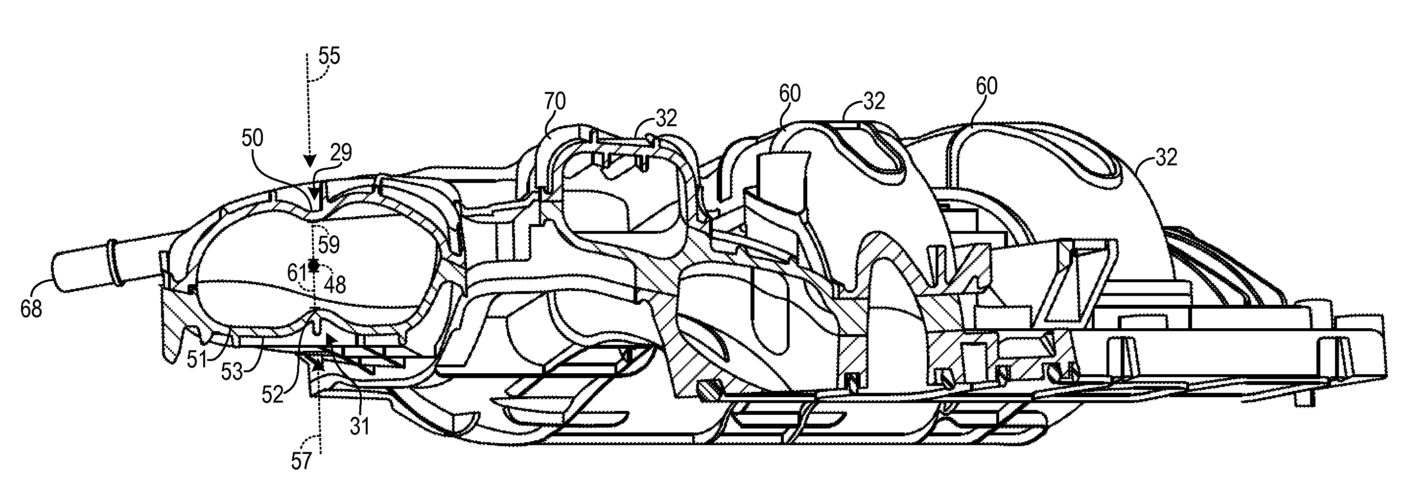
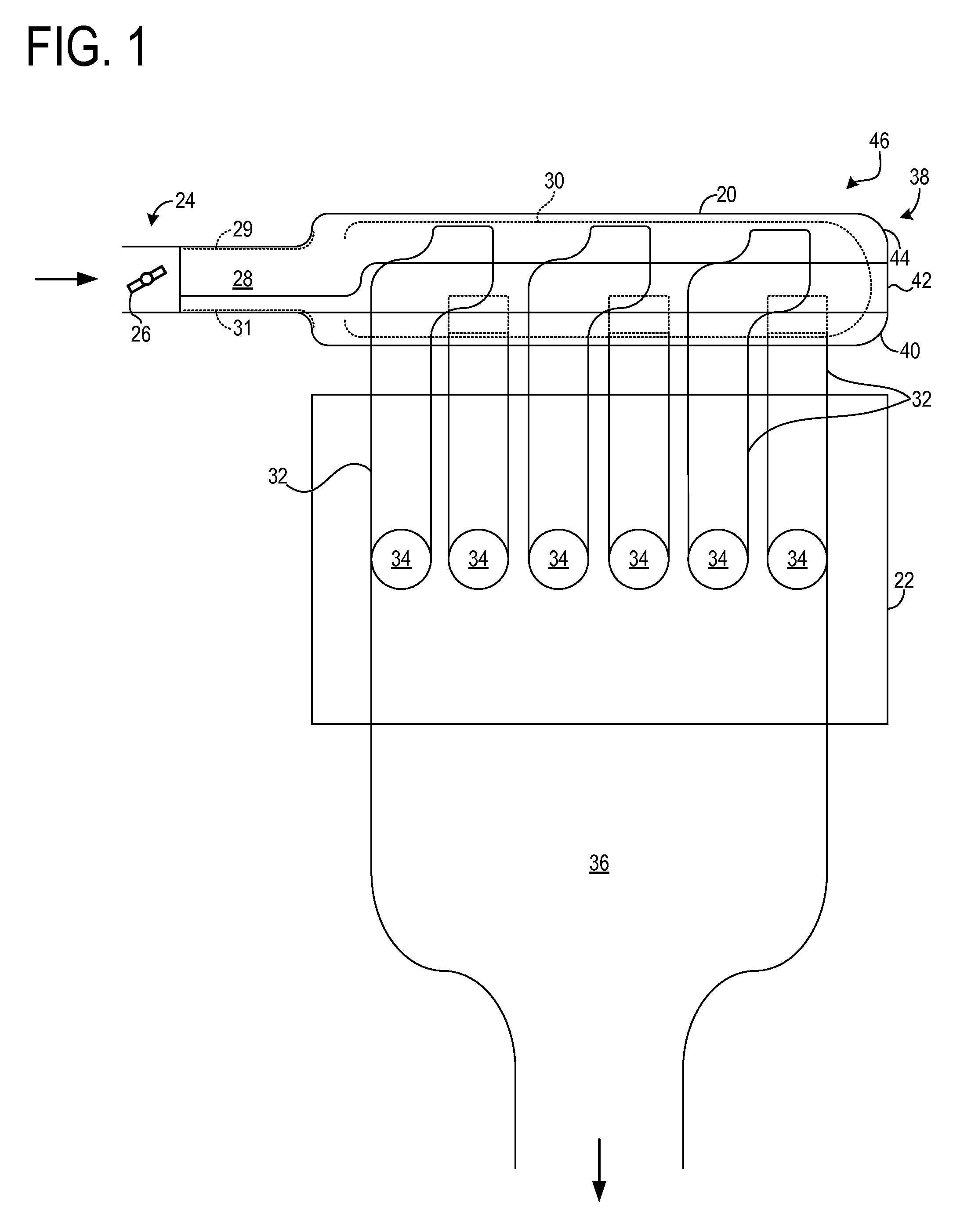
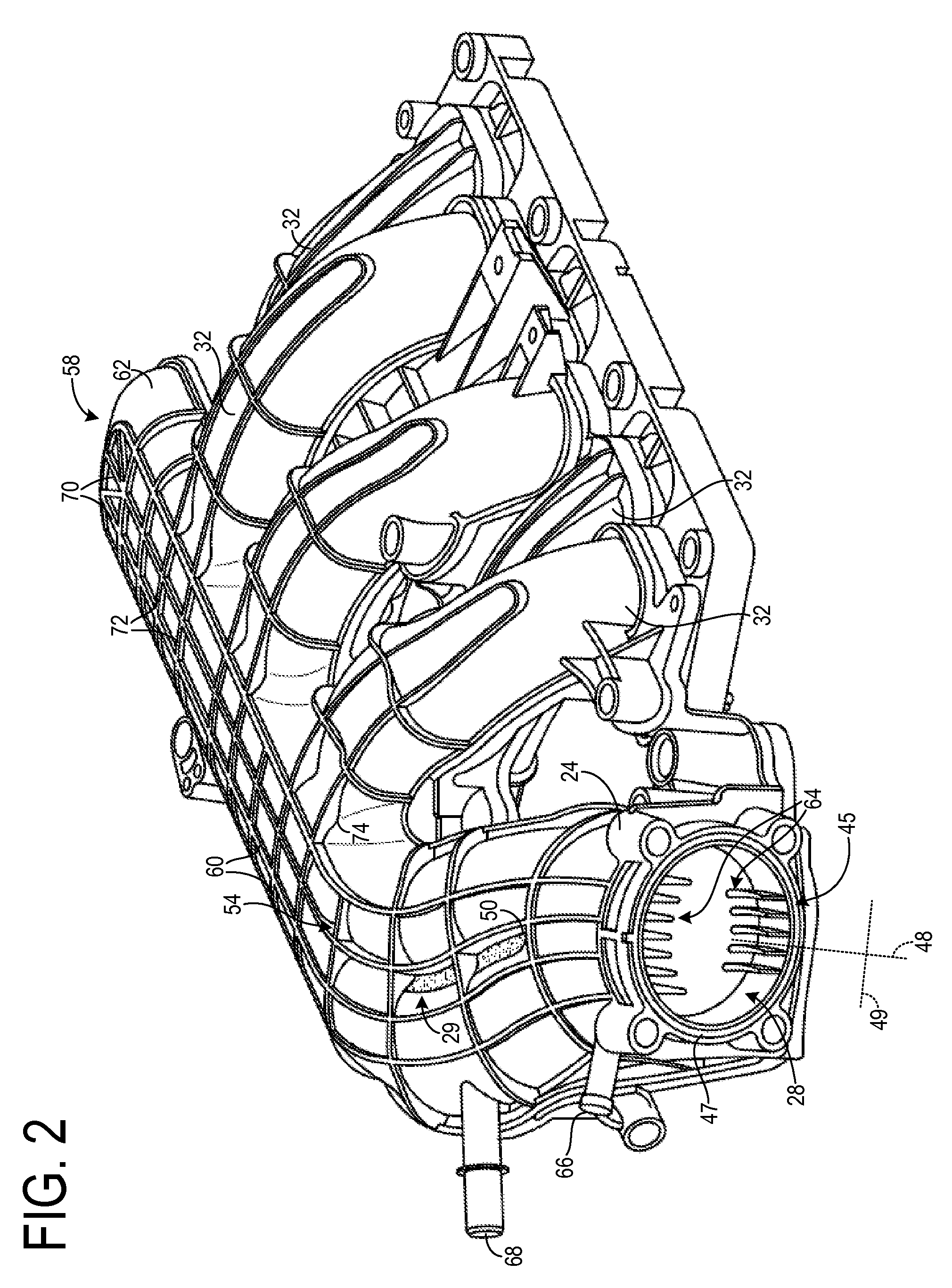
[0019]The following description relates to an intake manifold having a first and a second non-linear indentation oppositely positioned from one another aligned along a central length of a non-linear manifold inlet passage and configured to reduce noise, vibration, and harshness (NVH) associated with the manifold and its inlet. The manifold may be an intake manifold or other type of manifold. The first indentation may protrude radially inward at a first inflection point in a first direction, while the second indentation may protrude radially inward at a second inflection point in a second direction substantially anti-parallel to the first direction. The wall thickness of the manifold may be maintained at the first and second inflection points. In this way, NVH associated with the manifold and its inlet may be reduced while sufficient pressure and sealing are attained without adding weight, cost, or complexity to the manifold.

[0020]The present disclosure may use perspective-based desc...


PUM

PropertyMeasurementUnit
thicknessaaaaaaaaaa
lengthaaaaaaaaaa
diameteraaaaaaaaaa

Abstract

Various systems for reducing noise, vibration, and harshness in an intake manifold are provided. In one example, an intake manifold includes one or more runners, a plenum fluidically coupled to the one or more runners, an inlet having a wall thickness, and a first and a second indentation, where the first indentation protrudes radially inward at a first inflection point in a first direction, the second indentation protrudes radially inward at a second inflection point in a second direction substantially anti-parallel to the first direction, and the wall thickness is maintained at the first and second inflection points. In this way, noise, vibration, and harshness associated with the intake manifold and its inlet may be reduced without additional weight, cost, or complexity.

Description

FIELD[0001]The disclosure relates generally to intake manifolds, and systems for intake manifolds.BACKGROUND AND SUMMARY[0002]In combustion engines, intake manifolds provide air or air / fuel mixtures to cylinders. A throttle body coupled to an intake manifold at a first end may control the manifold pressure and flow delivered to the cylinders. The flow from the throttle body enters a plenum, which in turn directs the flow to a plurality of runners in fluidic communication with intake ports of the cylinders. In addition, intake manifolds are designed to reduce noise, vibration, and harshness (NVH) generated by the flow.[0003]U.S. Pat. App. No. 2010 / 0326395 describes an intake manifold cover with braces integral to its exterior, provided to enhance the structure of the cover and reduce NVH. The braces extend upwardly and outwardly from brace flange portions which themselves extend outwardly from the intake manifold and are disposed between adjacent intake runner ports. The braces are i...

Claims


Application Information

Patent Timeline
Patent Type & Authority Patents(United States)
IPC IPC(8): F02M35/10F02B27/00F02M35/104F02M35/112
CPCF02M35/1045F02M35/10039F02M35/10321F02M35/10354F02M35/112F02B27/00F02M35/1227
Inventor KULKARNI, MILIND B.
Owner FORD GLOBAL TECH LLC
Why Eureka
Try Eureka