Methods and apparatus for controlling a fluid damper

a technology of fluid dampers and dampers, which is applied in the direction of shock absorbers, springs/dampers, functional characteristics, etc., can solve the problems of mechanical systems using variable viscosity fluids that are not capable of handling corresponding dynamic loads, and the use of variable viscosity fluids

Active Publication Date: 2015-02-17
FOX FACTORY
View PDF16 Cites 76 Cited by
  • Summary
  • Abstract
  • Description
  • Claims
  • Application Information

AI Technical Summary

Problems solved by technology

There are problems arising from the use of variable viscosity fluids, like MR fluid in mechanical applications.
Mechanical systems using such fluids may not be capable of handling corresponding dynamic loads.
Another problem with the MR fluid is its abrasiveness.
This abrasiveness is caused by the ferrous particles suspended in the oil as they can have a sandpaper effect on all of the moving parts.
Mechanical systems employing such fluids may be rapidly worn out.

Method used


Image

  • Methods and apparatus for controlling a fluid damper
  • Methods and apparatus for controlling a fluid damper
  • Methods and apparatus for controlling a fluid damper

Examples


Embodiment Construction

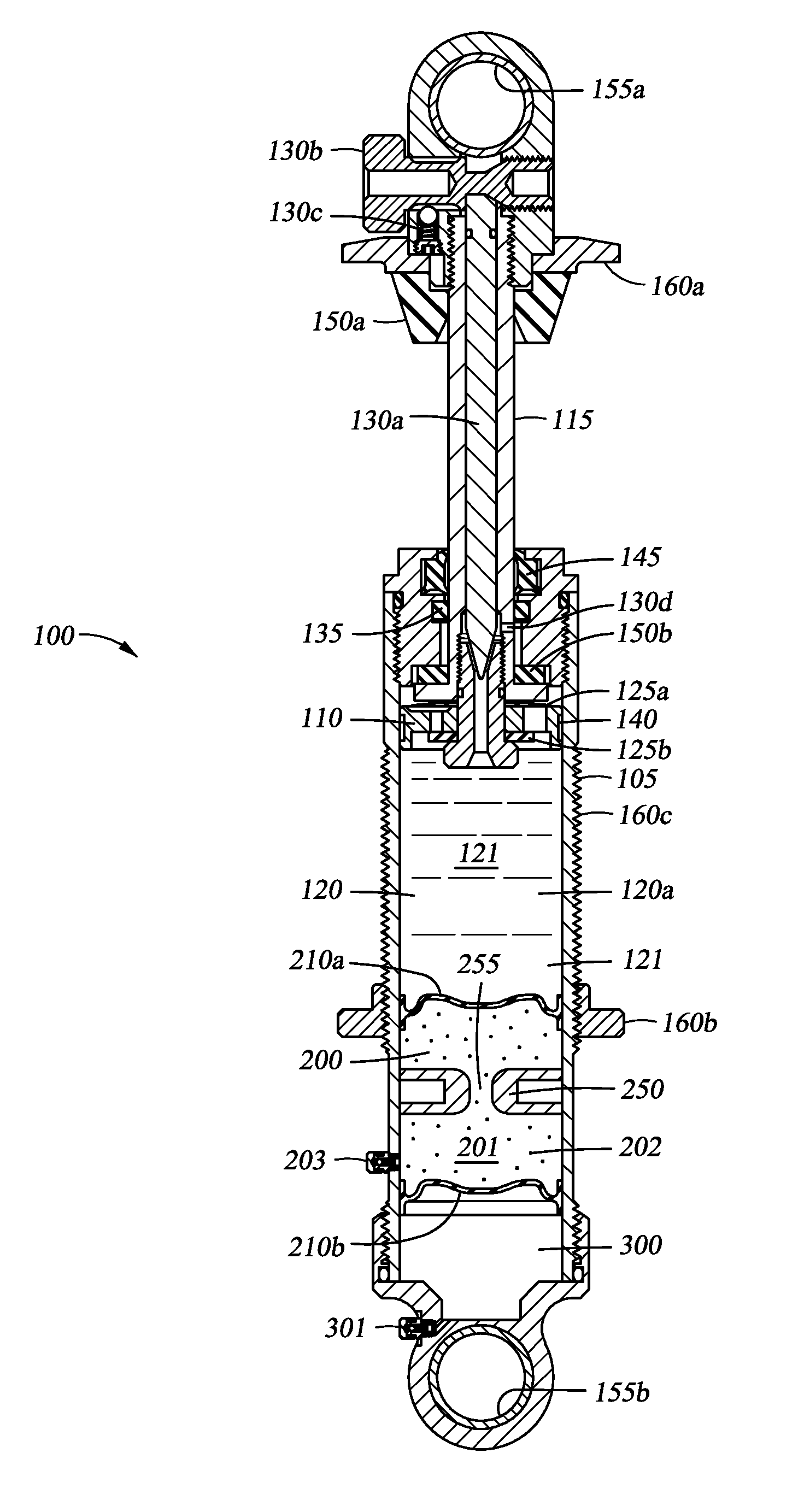
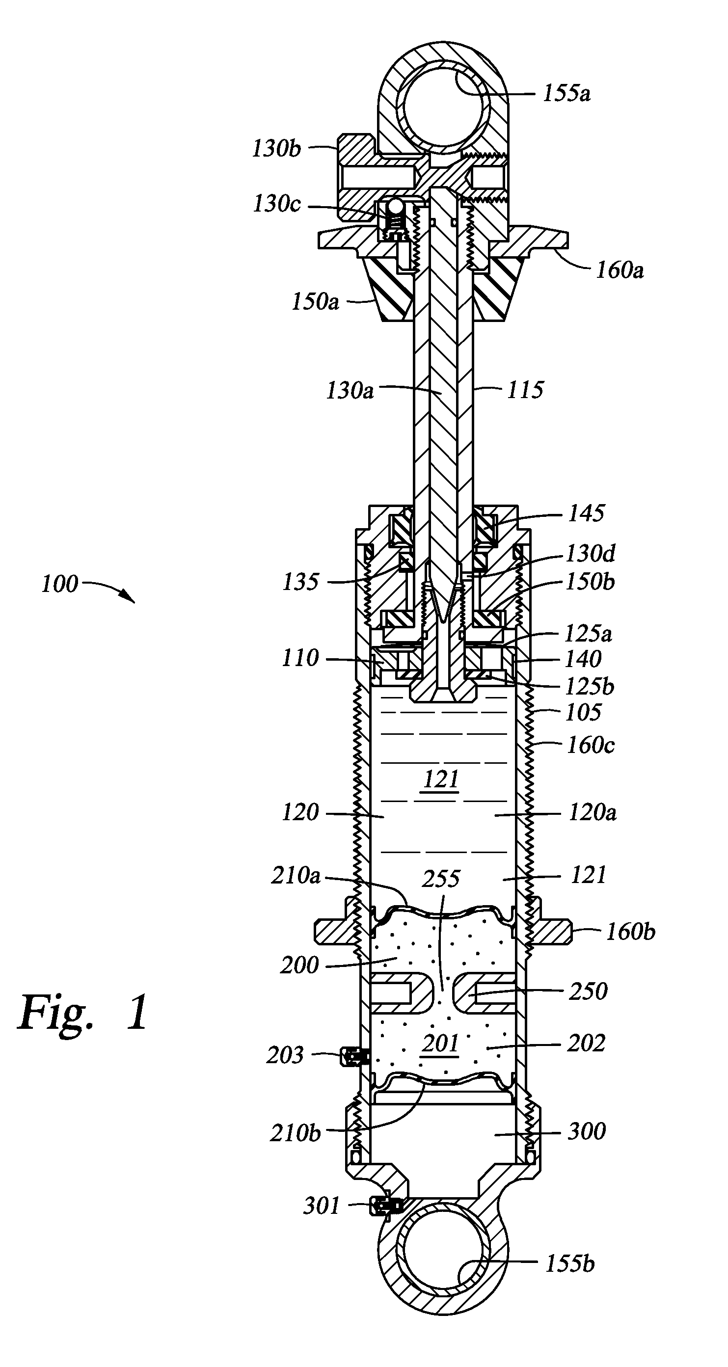
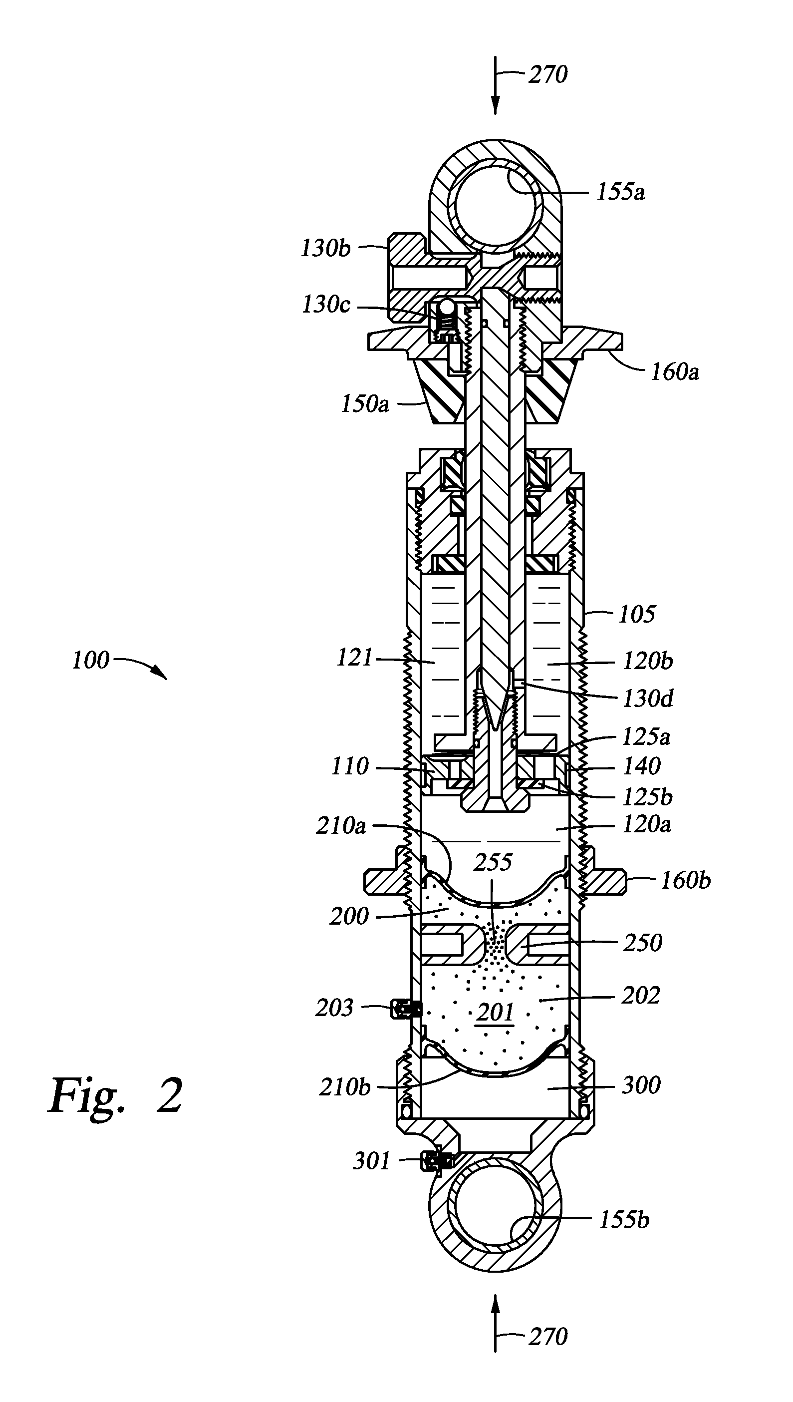
[0014]FIG. 1 is a section view of a damper 100. The damper includes a housing 105 as well as a piston 110 and rod 115 for reciprocating within the housing in compression and retraction or “rebound” strokes. The housing includes a first chamber 120 filled with a first fluid 121, and the chamber is dividable into a compression side 120a (shown in FIG. 1) and a rebound side 120b (FIG. 2). The piston 110 is often provided with fluid pathways therethrough including shims 125a, b which permit fluid to pass between sides 120a, 120b of the first chamber 120 while providing predetermined damping flow resistance. For example, during a compression stroke shims 125a are displaceable to permit fluid to move through the piston in an upwards direction. Similarly, during a rebound stroke, shims 125b permit fluid to flow back into the compression side 120a of the first chamber 120. In addition to shims 125a, fluid metering in a compression stroke is controlled by a valve assembly consisting of an ax...


PUM


Abstract

A method and apparatus for a fluid damper comprising a first fluid-filled chamber, a second chamber filled with a fluid having variable flow characteristics and at least partially displaceable by the first fluid, and a gas chamber, the gas chamber compressible due to the displacement of the second chamber. In one embodiment, the fluid in the second chamber is a variable rheology fluid.

Description

CROSS-REFERENCE TO RELATED APPLICATIONS[0001]This application claims priority to and benefit of U.S. provisional patent application Ser. No. 61 / 250,927, filed Oct. 13, 2009, which is herein incorporated by reference.BACKGROUND OF THE INVENTION[0002]1. Field of the Invention[0003]The present invention relates to shock absorbers for vehicles. More particularly, the disclosure relates to fluid dampers. More particularly still, the disclosure relates to methods and apparatus for controlling and managing dampening through the selective use of dampening fluid having variable flow characteristics.[0004]2. Description of Related Art[0005]Magneto rheological fluid (MR fluid) is a variable character fluid comprising a (e.g. colloid like) suspension of micrometer-sized particles in a carrier fluid, often a type of oil. When subjected to a magnetic field, the fluid greatly increases its apparent viscosity and / or shear strength. The particles, which are typically micrometer or nanometer scale sp...

Claims


Application Information

Patent Timeline
Patent Type & Authority Patents(United States)
IPC IPC(8): F16F9/53F16F9/06
CPCF16F9/53F16F9/066B60G15/12B60G17/08F16F9/061B60G15/062B60G2202/24B60G2206/41B60G2500/10B60G2600/22B60G2800/162F16F9/535F16F2222/06F16F2224/045F16F2228/066
Inventor MARKING, JOHN
Owner FOX FACTORY
Why Eureka
Try Eureka