Magnetic field measuring apparatus
a magnetic field and measuring device technology, applied in the direction of magnetic field measurement using magneto-optic devices, instruments, reradiation, etc., can solve the problems of low measurement precision and the need for expensive magnetic shields, and achieve the effect of improving the accuracy of the magnetic field gradient measurement using the light pumping method
- Summary
- Abstract
- Description
- Claims
- Application Information
AI Technical Summary
Benefits of technology
Problems solved by technology
Method used
Image
Examples
embodiments
Overall Configuration
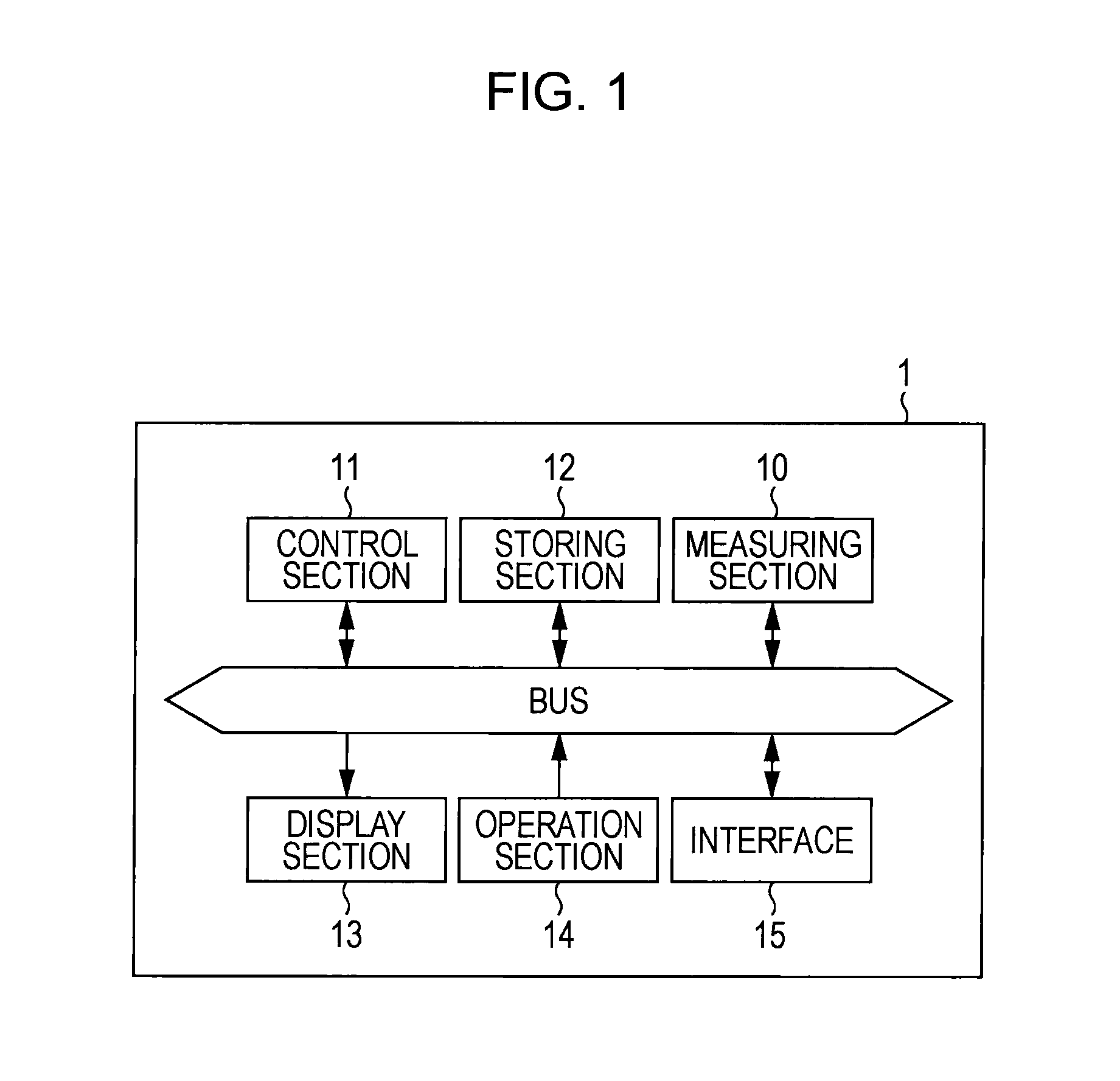
[0030]FIG. 1 is a block diagram showing a configuration of a magnetic field measuring apparatus 1. The magnetic field measuring apparatus 1 is an apparatus that measures the strength of a magnetic field that is generated from an object being measured using a light pumping method, and has the measuring section 10, the control section 11, the storing section 12, the display section 13, the operation section 14 and the interface 15. The measuring section 10 has each of the configurations that measures the strength of the magnetic field and performs control of the measuring start and finish by the control section 11. The measuring section 10 outputs polarized light rotation angle information to the control section 11 during measuring. Description will be given below regarding the detail of the measuring section 10 and the polarized light rotation angle information.
[0031]The control section 11 has an arithmetic processing circuit such as CPU (Central Processing Unit)...
modified embodiment
[0081]As described above, description has been given concerning the embodiment of the invention, however the invention can be modified in various examples as described below.
first modified example
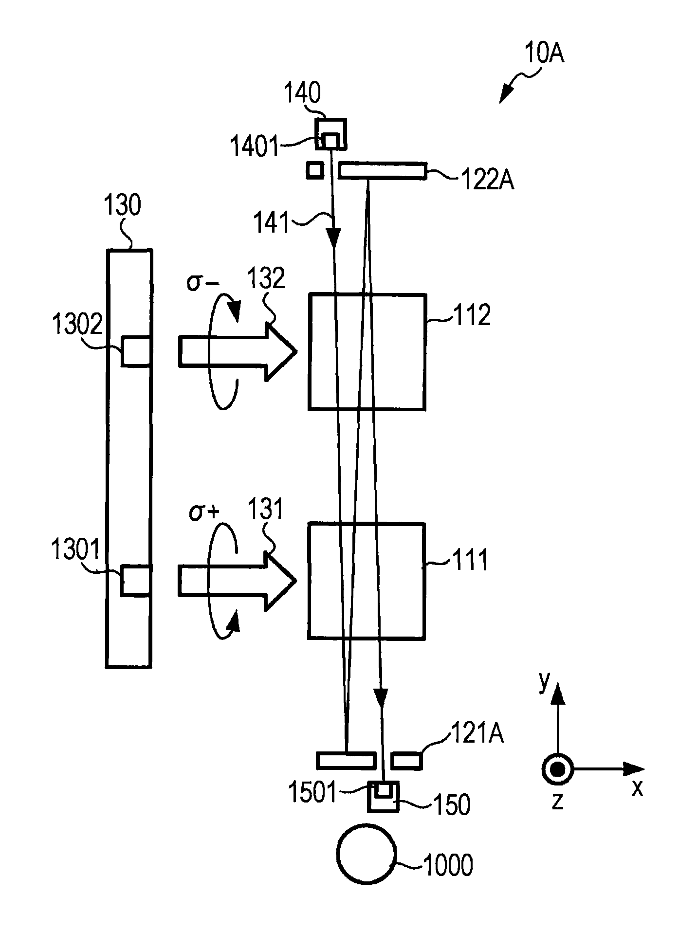
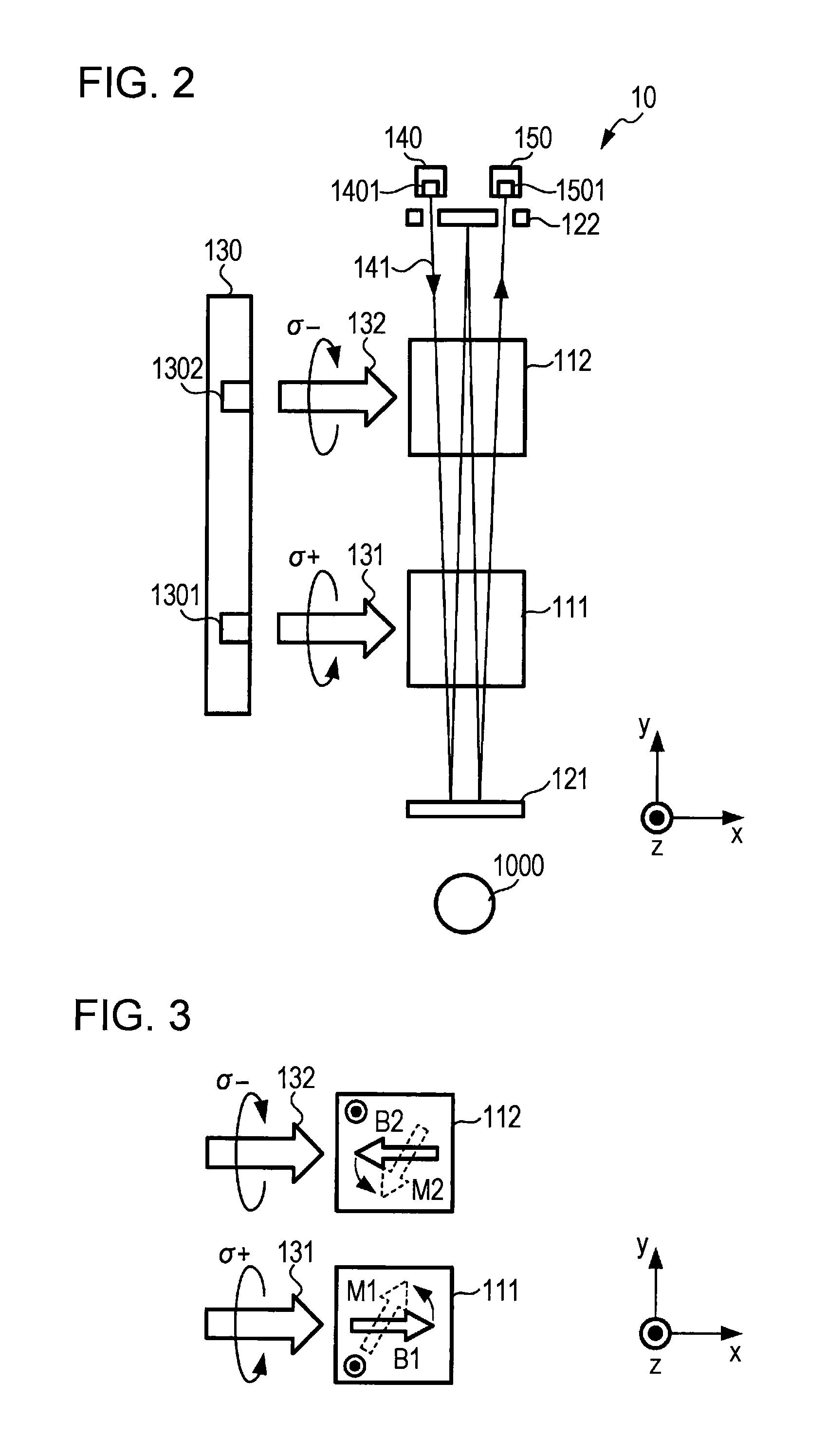
[0082]In the above-described embodiment, the ejecting section 1401 and the light receiving section 1501 are positioned in the same side with respect to the first gas cell 111 and the second gas cell 112, however they may be positioned in different sides to each other.
[0083]FIG. 7 is a drawing showing a configuration of a measuring section 10A according to a first modified example. The measuring section 10A uses the reflecting mirrors 121A and 122A instead of the reflecting mirrors 121 and 122 of the measuring section 10 in the embodiment, and the position of the light receiving section 1501 is on the side opposite to the position of the ejecting section 1401 through the first gas cell 111 and the second gas cell 112.
[0084]In the case of this configuration, the relation between positive and negative of the y-axis direction is different when the light receiving section 1501 receives the probe light 141, so that the process is performed reversing positive and negative as the above-desc...
PUM
 Abstract
Description
Claims
Application Information
 - R&D
- Intellectual Property
- Life Sciences
- Materials
- Tech Scout
- Unparalleled Data Quality
- Higher Quality Content
- 60% Fewer Hallucinations
Browse by: Latest US Patents, China's latest patents, Technical Efficacy Thesaurus, Application Domain, Technology Topic, Popular Technical Reports.
© 2025 PatSnap. All rights reserved.Legal|Privacy policy|Modern Slavery Act Transparency Statement|Sitemap|About US| Contact US: help@patsnap.com


