Weapon mounted light and operation thereof

a flashlight and multi-functional technology, applied in the direction of electric lighting with batteries, lighting and heating devices, lighting support devices, etc., can solve the problems of affecting the operation of the flashlight, and the flashlight may slide or rotate within the band, so as to improve the method of compact and reliable mounting of the flashlight onto the firearm, easy to operate, and consistent and quick engagement

Active Publication Date: 2015-02-24
EMISSIVE ENERGY A DELAWARE
View PDF16 Cites 9 Cited by
  • Summary
  • Abstract
  • Description
  • Claims
  • Application Information

AI Technical Summary

Benefits of technology

[0008]The operational modes of the flashlight are controlled by a single push button and a selector switch. To facilitate a highly compact design the flashlight employs two circuitry arrangements positioned remote from one another and in communication with one another via a single conductive trace. The push button consists of a single momentary switch while the selector includes a magnet and a Hall Effect sensor that operate together to toggle between an open and closed position. In this manner the selector switch, when moved between an open and closed position, provides a signal to the circuitry at the rear of the flashlight to operate at a first signal frequency or a second signal frequency.
[0010]Accordingly, it is an object of the present invention to provide a flashlight having a housing that includes a mounting interface that is integrated into the construction of its housing that provides an improved method of compactly and reliably mounting a flashlight onto a firearm. It is a further object of the present invention to provide an interfaceable flashlight assembly that is multi-functional, easy to operate and provides an improved engagement method for firearms that has the ability to consistently and quickly engage, and provide accurate alignment, while providing a reduced profile, thereby reducing potential interference with other devices and attachments. It is still a further object of the present invention to provide a device that provides multi-functionality in an improved flashlight construction that is easier to operate and exhibits a high degree of reliability even in the most rugged environment.

Problems solved by technology

The difficulty encountered with this construction is that in some cases it creates a greater opportunity for the flashlight and mounting assembly to be caught on clothing or brush while the firearm is being carried, thereby knocking the flashlight out of alignment, dislodging the flashlight from the firearm or damaging the flashlight.
Further, the interface between the outer tubular housing and the mounting band leaves the potential that the flashlight may slide or rotate within the band requiring frequent repositioning.
While this may be acceptable for a sport type firearm, it is not acceptable for a firearm employed for field use, such as hunting or combat environments where immediate, fully aligned use of the flashlight assembly is required.
Such pressure not only contributes to the displacement of the flashlight within the mounting band but also requires a user to move their thumb in an awkward manner to operate the flashlight.
Other difficulties with such flashlights include the fact that they were typically single function devices that had to be exchanged for a different flashlight should the need for an additional function arise, such as for example, in infra-red applications.
In addition, should a flashlight include multi-functional features, often the controls are small and fussy making them difficult to operate in the typical military environment where the user is often wearing gloves.
In these applications small buttons, sliders and knobs are nearly impossible to operate in a reliable fashion.

Method used


Image

  • Weapon mounted light and operation thereof
  • Weapon mounted light and operation thereof
  • Weapon mounted light and operation thereof

Examples


Embodiment Construction

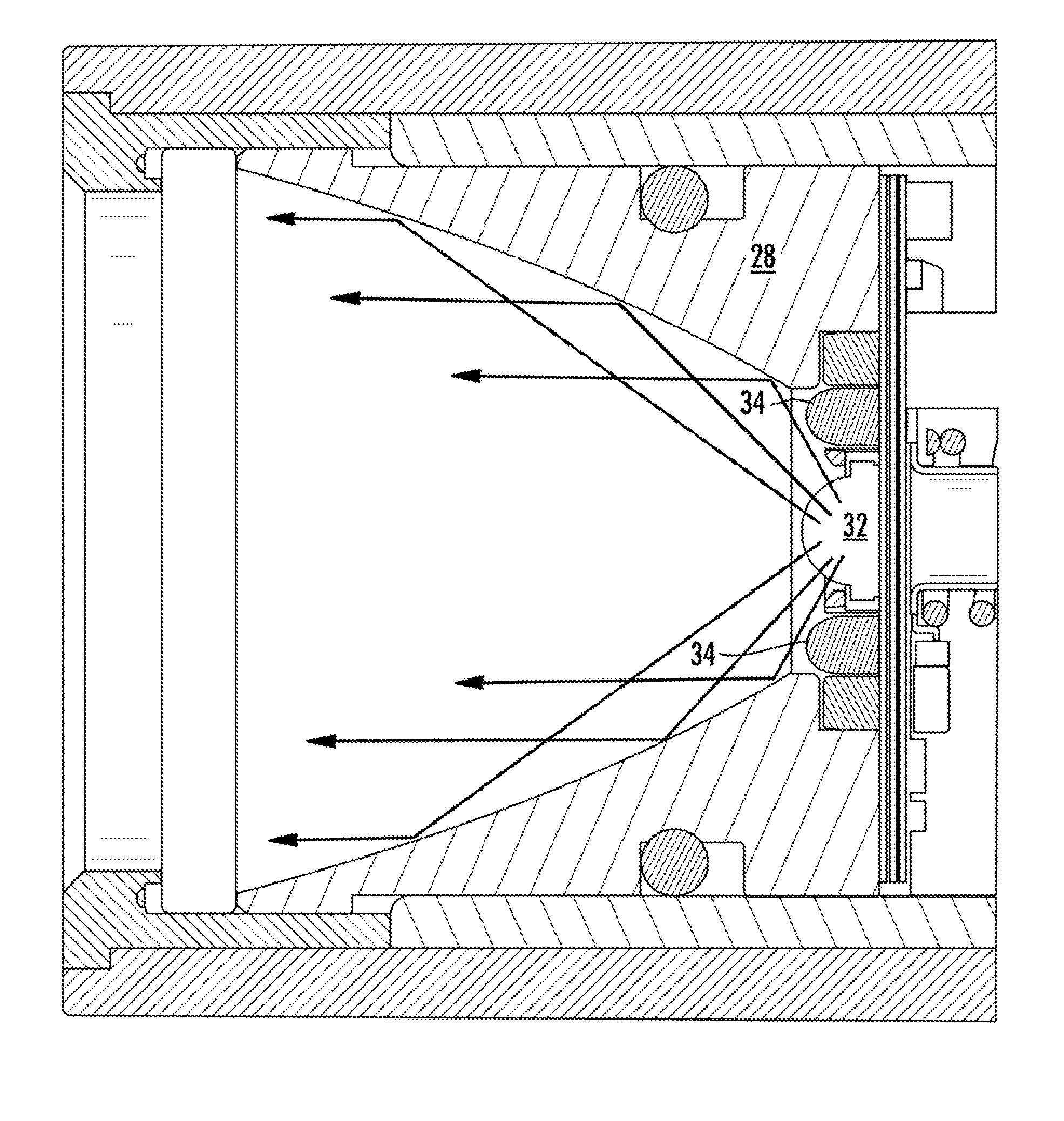
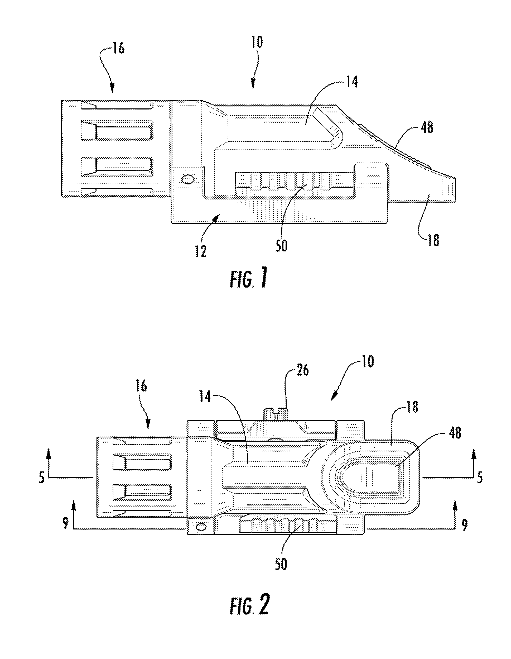
[0026]Now referring to the drawings, a flashlight assembly is shown and generally illustrated in the figures. As can be seen in FIGS. 1 and 2, the flashlight assembly 10 includes an interface 12 integrated into the housing 14 thereof to facilitate mounting of the flashlight 10 to the dovetail rail on a modern combat weapon. Generally, the outer body of the flashlight includes a head 16 mounted to a flashlight housing body at one end and a tapered tail 18 extending outwardly at the other end of the body. Further, the flashlight 10 includes protrusions extending from the side of the body that serve as an integrated interface 12 for interfacing the flashlight 10 with a firearm.

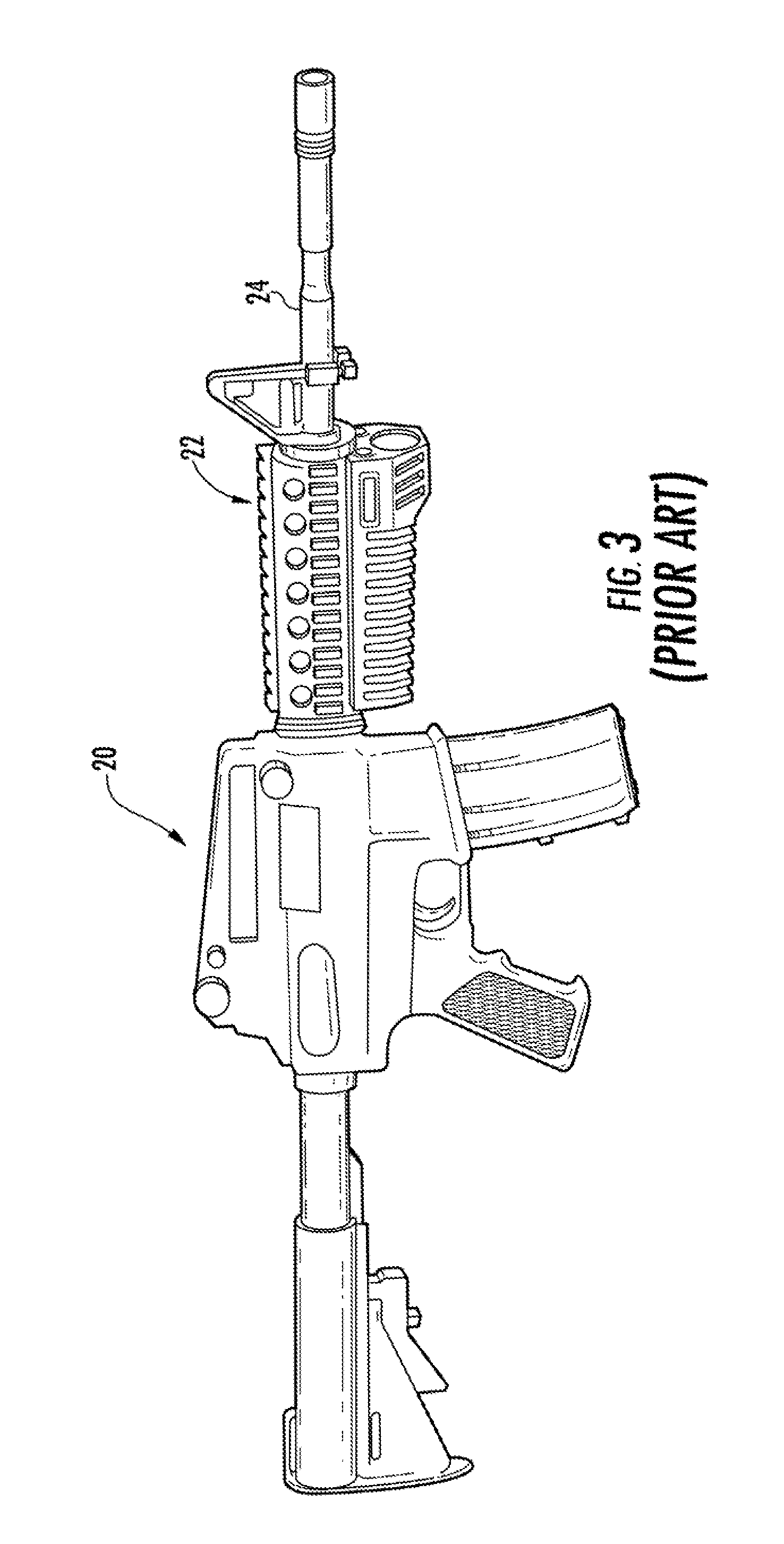
[0027]As depicted at FIG. 3, modern type firearms 20 generally include an interface rail integrated 22 thereon for the mounting of auxiliary devices. Additionally, there are several supplemental rail systems that mount onto such firearms 20 and extending along and around the barrel 24 to provide additional interf...


PUM


Abstract

A novel flashlight assembly that includes an interface integrated into the housing thereof to facilitate mounting of the flashlight to the dovetail rail on a modern combat weapon. The outer body of the flashlight includes a head mounted to a flashlight body at one end and a tapered tail extending outwardly at the other end of the body. Further, the flashlight includes a clamping interface that is a seamless and integrated feature of the outer housing of the flashlight itself for interfacing the flashlight with a firearm. The operational modes of the flashlight are controlled by a single push button and a selector switch. To facilitate a highly compact design the flashlight employs two circuitry arrangements positioned remote from one another and in communication with one another via a single conductive trace to operate at a first signal frequency or a second signal frequency.

Description

CROSS-REFERENCE TO RELATED APPLICATIONS[0001]This application is related to and claims priority from earlier filed U.S. Provisional Patent Application No. 61 / 418,944, filed Dec. 2, 2010.BACKGROUND OF THE INVENTION[0002]The present invention relates generally to a multi-function flashlight assembly that is configured in a manner that includes an integrated weapon mounting interface. More specifically, the present invention relates to a compact, high intensity, multi-purpose flashlight assembly that includes a high level of functionality in connection with an integrated weapon mounting interface, thereby making the flashlight capable of being utilized as an accessory for a variety of devices such as standard military style rail type mount, for example.[0003]In the prior art, flashlights for use in military applications have typically been constructed in a standard fashion utilizing a tubular outer housing. As a consequence, in order to facilitate mounting of the flashlight onto other ...

Claims


Application Information

Patent Timeline
Patent Type & Authority Patents(United States)
IPC IPC(8): F41G1/35F41G11/00
CPCF41G11/004F21L4/00F21V21/0885F21V23/0421
Inventor GALLI, ROBERT D.O'BRIEN, CHRISTOPHER J.
Owner EMISSIVE ENERGY A DELAWARE
Why Eureka
Try Eureka