Mounting rail bus system

a bus system and rail technology, applied in the direction of electrical equipment, support structure mounting, coupling device connection, etc., can solve the problems a and achieve the effects of reducing system production costs, reducing power, and small multiplicity of parts

Active Publication Date: 2015-02-24
WEIDMULLER INTERFACE GMBH & CO KG
View PDF22 Cites 13 Cited by
  • Summary
  • Abstract
  • Description
  • Claims
  • Application Information

AI Technical Summary

Benefits of technology

[0011]According to a more specific object of the invention, each bus device has contact pins for the transmission and / or manipulation of electrical power supply output and / or with at least one printed circuit board with strip conductors for the transmission of electrical data and / or control signals with preferably reduced power when compared to the power supply output. Here, every contact pin and every strip conductor of the printed circuit board is in each case connected with a double bushing contact element. All double bushing contact elements are, in particular, made identical and can be used both for power transmission and for data transmission, something that results in a rather small multiplicity of parts and reduces the system production costs.
[0012]Another advantage consists in the fact that the double bushing contact elements are made both for the transmission of electrical power supply and for the transmission of electrical data and / or control systems of a lesser power output. Therefore, they can be used both for the connection of the contact pins and strip conductors and for the electrical connection of a module which is to be allocated as bus partner. In that way, one can save construction space. A compact design also results when the second bushing segments of the double bushing contact element are arranged essentially orthogonally with respect to the first bushing segments that extend in the longitudinal direction along the mounting rail.

Problems solved by technology

All double bushing contact elements are, in particular, made identical and can be used both for power transmission and for data transmission, something that results in a rather small multiplicity of parts and reduces the system production costs.

Method used


Image

  • Mounting rail bus system
  • Mounting rail bus system
  • Mounting rail bus system

Examples


Embodiment Construction

[0035]Functional units and structural elements with identical reference numbers indicate identical or similar functions. The following explanation relates to a particularly preferred exemplary embodiment to which, however, the invention is not restricted.

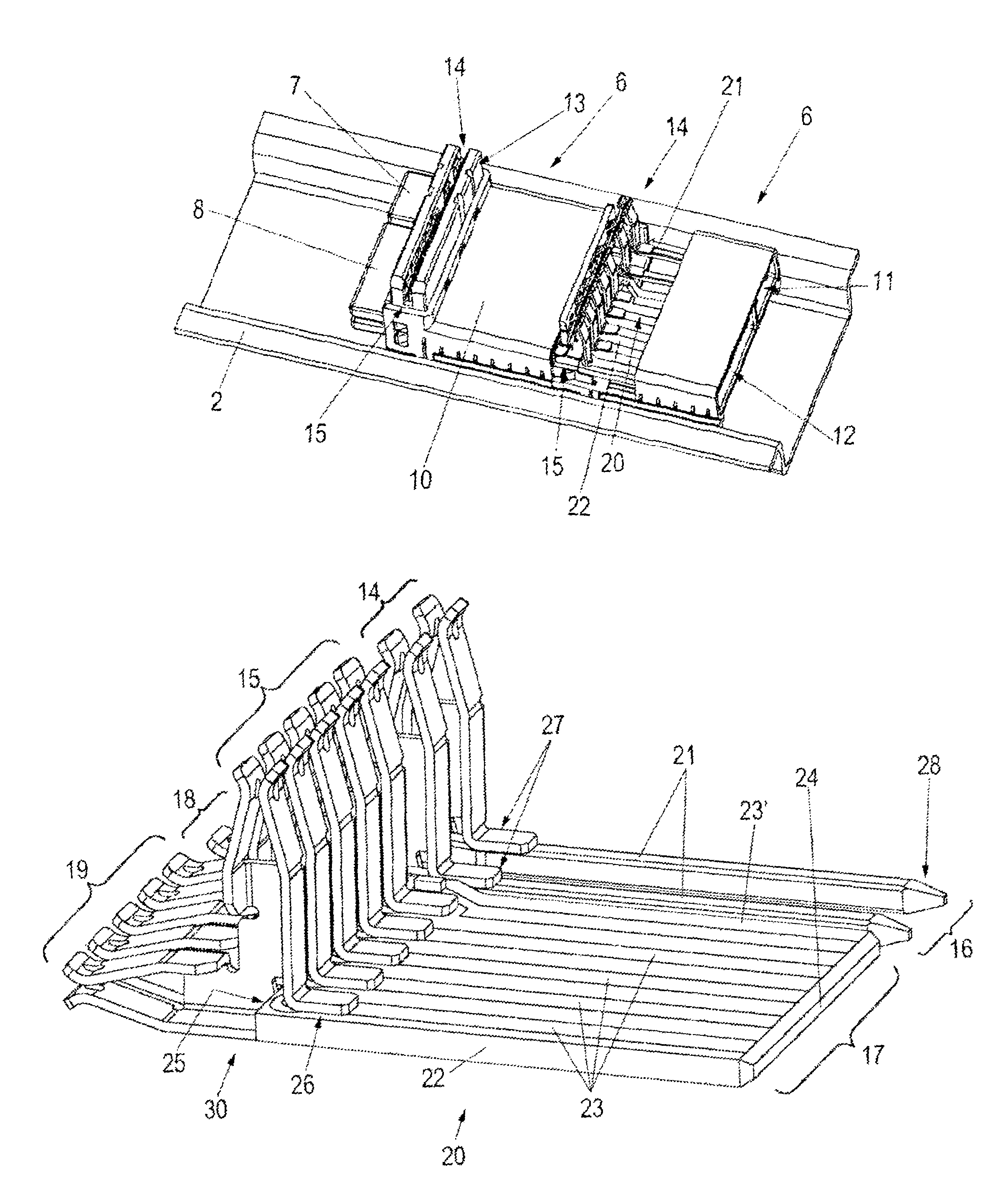
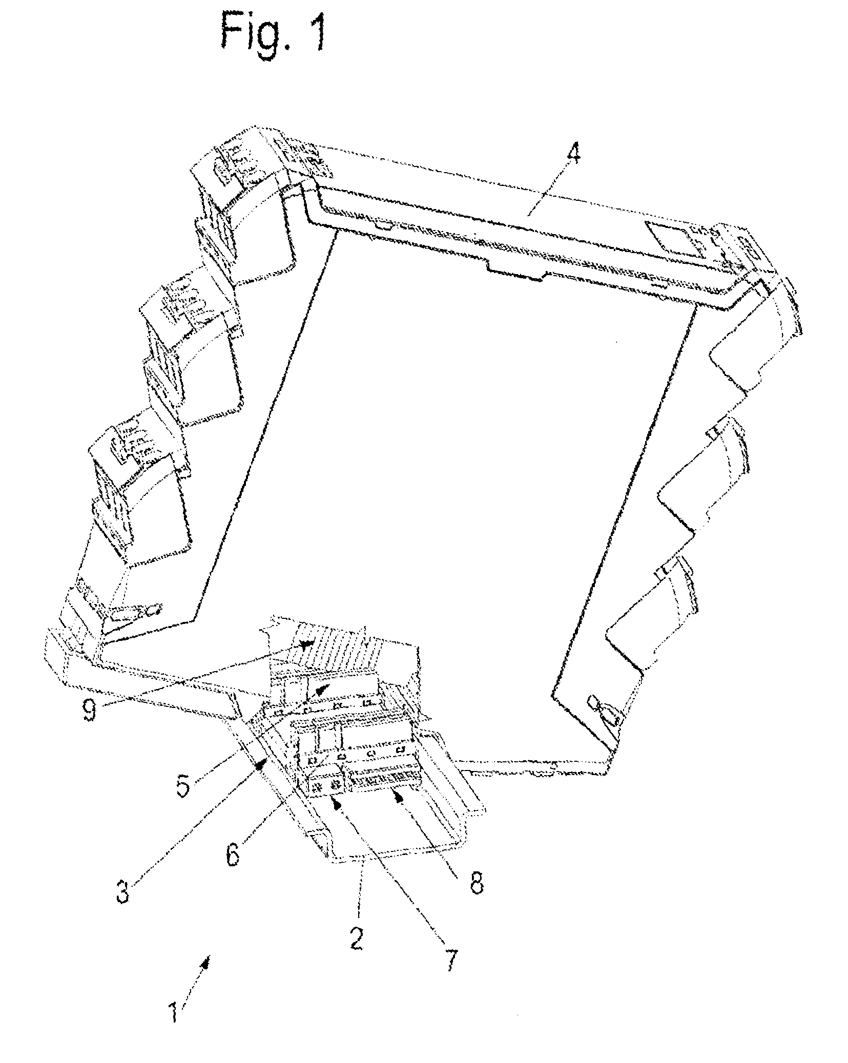
[0036]Referring first to FIG. 1, the mounting rail system 1 comprises a mounting rail 2 that in this case is made as a so-called top hat rail and that has a station bus 3 with at least two mutually connected bus members 6. A module 4, which in this case has various conductor connections (for example, terminal connections) and electronic switching functions that are not explained in any greater detail, can be stuck upon or inserted into the bus members and can be connected with the bus members. Module 4 is also referred to as bus partner of the station bus 3.

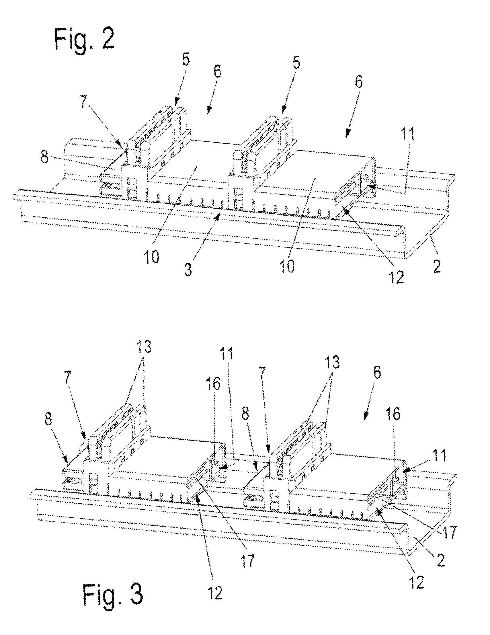
[0037]Bus members 6 are arranged inside mounting rail 2, for example, they are retained or clamped in a force-locking manner, and in each case, they have a plug-in site 5, which ...


PUM


Abstract

A mounting rail bus system for supplying power voltage and data signals to a plurality of modules, including a plurality of longitudinally-arranged bus devices mounting the modules in parallel spaced transverse relation on a mounting rail, each of the bus devices including a printed circuit board having parallel strip conductors for transmitting data signals, and a pair of power contact pins for transmitting a power voltage, characterized by the provision of a plurality of generally L-shaped double bushing contact elements have module bush segments for respectively connecting the strip conductors and the contact pins of the bus device with the associated module, and orthogonally arranged partner bush segments for connecting together the strip conductors and pin contacts of adjacent bus devices, respectively, whereby power voltage and data signals are transmitted from the bus device both to the associated module and to the adjacent partner bus device.

Description

REFERENCE TO RELATED APPLICATIONS[0001]This application is a continuation of the International application No. PCT / EP2011 / 056953 filed May 2, 2011, based on the German priority application No. DE10 2010 016 865.3 filed May 10, 2010.BACKGROUND OF THE INVENTION[0002]1. Field of the Invention[0003]A mounting rail bus system for supplying power voltage and data signals to a plurality of modules, including a plurality of longitudinally-arranged bus devices mounting the modules in parallel spaced transverse relation on a mounting rail, each of the bus devices including a printed circuit board having parallel strip conductors for transmitting data signals, and a pair of power contact pins for transmitting a power voltage, characterized by the provision of a plurality of generally L-shaped double bushing contact elements have module bush segments for respectively connecting the strip conductors and the contact pins of the bus device with the associated module, and orthogonally arranged part...

Claims


Application Information

Patent Timeline
Patent Type & Authority Patents(United States)
IPC IPC(8): H01R25/00H01R9/26H01R25/14H05K7/14
CPCH01R9/2675H01R9/2658H01R25/14H05K7/1478
Inventor GRIESE, BJOERNLANGE, STEPHANBOECKER, MARCKRONER, MICHAELSCHNUECKEL, MARKUSROSE, GORM
Owner WEIDMULLER INTERFACE GMBH & CO KG
Why Eureka
Try Eureka