Vacuum pump mounting structure

a technology for vacuum pumps and mounting structures, applied in the direction of valve drives, auxiliary lubrication, liquid fuel engines, etc., can solve the problems of inability to suppress vibration and noise, so as to achieve the effect of suppressing vibration and noise of an engin

Active Publication Date: 2015-03-03
SUZUKI MOTOR CORP
View PDF6 Cites 1 Cited by
  • Summary
  • Abstract
  • Description
  • Claims
  • Application Information

AI Technical Summary

Benefits of technology

[0008]It is therefore an object of the present invention to provide a vacuum pump mounting structure which can suppress vibration and noise of an engine.
[0012]According to the aspect of the embodiments of the present invention, the engine-upper side of the body portion of the vacuum pump is fixed to the cam housing-side boss portion which is formed in the cam housing, and the engine-lower side of the body portion of the vacuum pump is fixed to the cylinder head-side boss portion which is formed in the cylinder head. Consequently, since the body portion of the vacuum pump is fixed to both the cam housing and the cylinder head in a bridge manner, floating of the cam housing due to the force applied from the cam shaft can be suppressed with the body portion of the vacuum pump, thereby reliably securing the cam housing. As a result, it is possible to suppress vibration and noise of the engine caused by the cam housing or the cam shaft.
[0013]Further, when the cover for covering the vacuum pump to close the cylinder head and the cam housing is detachably attached to the cylinder head and the cam housing, it is possible to block the noise generated at the time of operating the vacuum pump.
[0014]In addition, when the timing gear for transmitting the rotation of the crankshaft is attached to the axial end portion of one of the two cam shafts, and the pump shaft of the vacuum pump is connected to the axial end portion of another of the two cam shafts at the same side as the timing gear attached, the body portion of the vacuum pump can be fixed to both the cylinder head and the cam housing within the cover in the bridge manner, while avoiding interference of the timing gear or the timing chain. Therefore, it is possible to save a space, while suppressing the vibration and noise of the engine.

Problems solved by technology

The cam housing may be floated by a force from the cam shaft, which leads to vibration and noise.
Since the body of the vacuum pump is simply attached to the cover in the vacuum pump mounting structure according to the related art, it is not possible to suppress the vibration and the noise.

Method used


Image

  • Vacuum pump mounting structure
  • Vacuum pump mounting structure
  • Vacuum pump mounting structure

Examples


Embodiment Construction

[0027]Reference will now be made in detail to the present embodiments of the present invention, examples of which are illustrated in the accompanying drawings, wherein like reference numerals refer to the like elements throughout. The embodiments are described below in order to explain the present invention by referring to the figures.

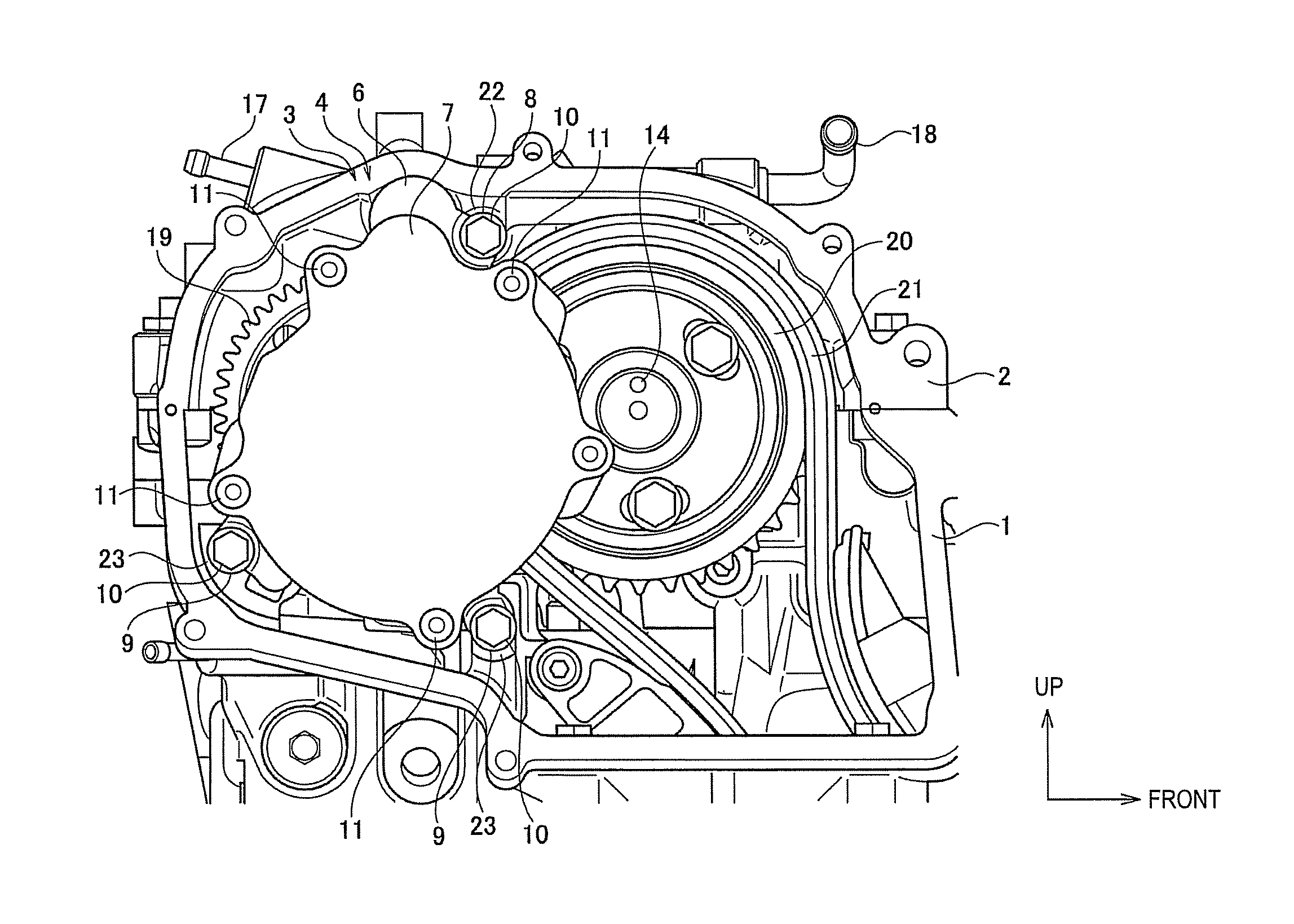
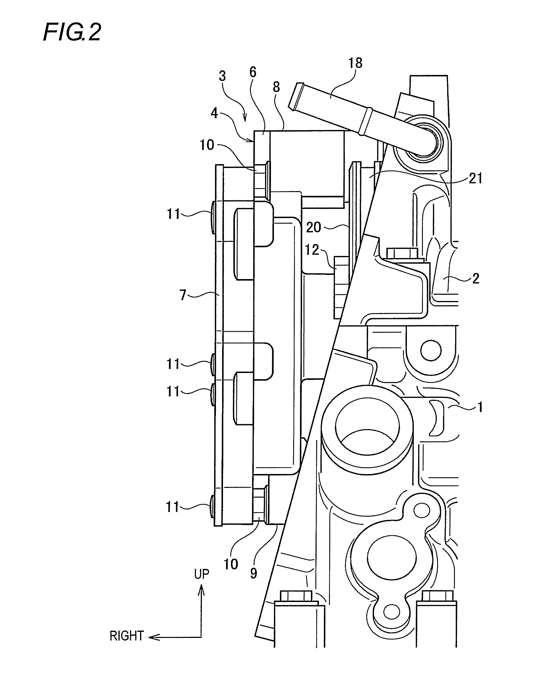
[0028]An embodiment of a vacuum pump mounting structure of the present invention will be described with reference to the accompanying drawings. FIG. 1 is a front view of an engine according to an embodiment of a vacuum pump mounting structure of the present invention, where a cover is detached. FIG. 2 is a side view of the engine illustrated in FIG. 1. FIG. 3 is a plan view of the engine illustrated in FIG. 1. FIG. 4 is a front view of the engine illustrated in FIG. 1, where the cover is attached. FIG. 5 is a plan view of the engine illustrated in FIG. 4. FIG. 6 is a front view of the engine, where a vacuum pump is detached from the state illustrated i...


PUM


Abstract

There is provided a vacuum pump mounting structure. A vacuum pump is connected to an axial end portion of a first cam shaft of an engine and is configured to be driven by the first cam shaft. The first cam shaft is disposed in a cylinder head. A cam housing rotatably supports the first cam shaft on the cylinder head. A cam housing-side boss portion and a cylinder head-side boss portion are formed in the cam housing. An engine-upper side of a body portion of the vacuum pump is fixed to the cam housing-side boss portion. An engine-lower side of the body portion of the vacuum pump is fixed to the cylinder head-side boss portion.

Description

CROSS-REFERENCE TO RELATED APPLICATIONS[0001]This application claims the benefit of Japanese Application No. 2013-018110, filed Feb. 1, 2013 in the Japanese Patent Office. All disclosures of the document(s) named above are incorporated herein by reference.BACKGROUND OF THE INVENTION[0002]1. Field of the Invention[0003]The present invention relates to a vacuum pump mounting structure for mounting a vacuum pump for use in a vehicle, and, more specifically, to a vacuum pump mounting structure in which a vacuum pump is connected to an axial end portion of a cam shaft of an engine and is configured to be driven by the cam shaft.[0004]2. Description of the Related Art[0005]A vacuum pump has a function of generating a negative pressure with rotation driving force, and the negative pressure is used for engine negative pressure driving parts such as a negative pressure booster device of a brake, and a VSV (Vacuum Switching Valve) for controlling a turbo charger. Recently, a cam shaft is typi...

Claims


Application Information

Patent Timeline
Patent Type & Authority Patents(United States)
IPC IPC(8): F02B41/00B60T17/02F01C21/10F01L1/02F02B67/06F04C18/344F04C25/02F04C29/00F04D29/60
CPCF04D29/60B60T17/02F01C21/10F04C25/02F04C29/0085F02B67/06F04C18/344F01L1/02F01L1/022F01L1/026F01L1/047F01L2001/0537
Inventor HASEGAWA, HIROKAZU
Owner SUZUKI MOTOR CORP
Why Eureka
Try Eureka