
Propfan engine

a propfan engine and engine body technology, applied in the direction of liquid fuel engine components, wind motors with parallel air flow, wind motors with perpendicular air flow, etc., can solve the problems of increased noise, aerodynamic losses and possible mechanical excitation, and reduced cruise speed

Active Publication Date: 2015-03-03
ROLLS ROYCE PLC
View PDF14 Cites 11 Cited by
  • Summary
  • Abstract
  • Description
  • Claims
  • Application Information

AI Technical Summary

Benefits of technology

The present invention is about the design of the part of the gas turbine engine that surrounds the rotors. This invention uses a specific shape of the engine to reduce the speed of the air that enters the rotors, which helps to increase the efficiency of the engine. This design also reduces the size of the engine at the front, which benefits the rotors. Overall, this design improves the performance of the engine.

Problems solved by technology

One problem with a conventional pusher propeller gas turbine engine 10 is that its cruise speed is limited to slightly below transonic, predominantly due to the drag rise encountered when flying at higher speeds.
The root has to be thick enough to guarantee the structural robustness of the blades given the high aerodynamic and mechanical loads acting on the propeller stages 23, 24, which disadvantageously adds significant weight to the engine 10.
This results in disadvantageous increased noise, aerodynamic losses and possible mechanical excitation, phenomena which it is desirable to avoid or at least limit.
However, due to the large maximum nacelle diameter of the GE36 required to achieve the diffusion, a large free-stream over-speed over the outer span of the propeller blades occurs and this is detrimental to the rotor efficiency.

Method used


Image

  • Propfan engine
  • Propfan engine
  • Propfan engine

Examples


Embodiment Construction

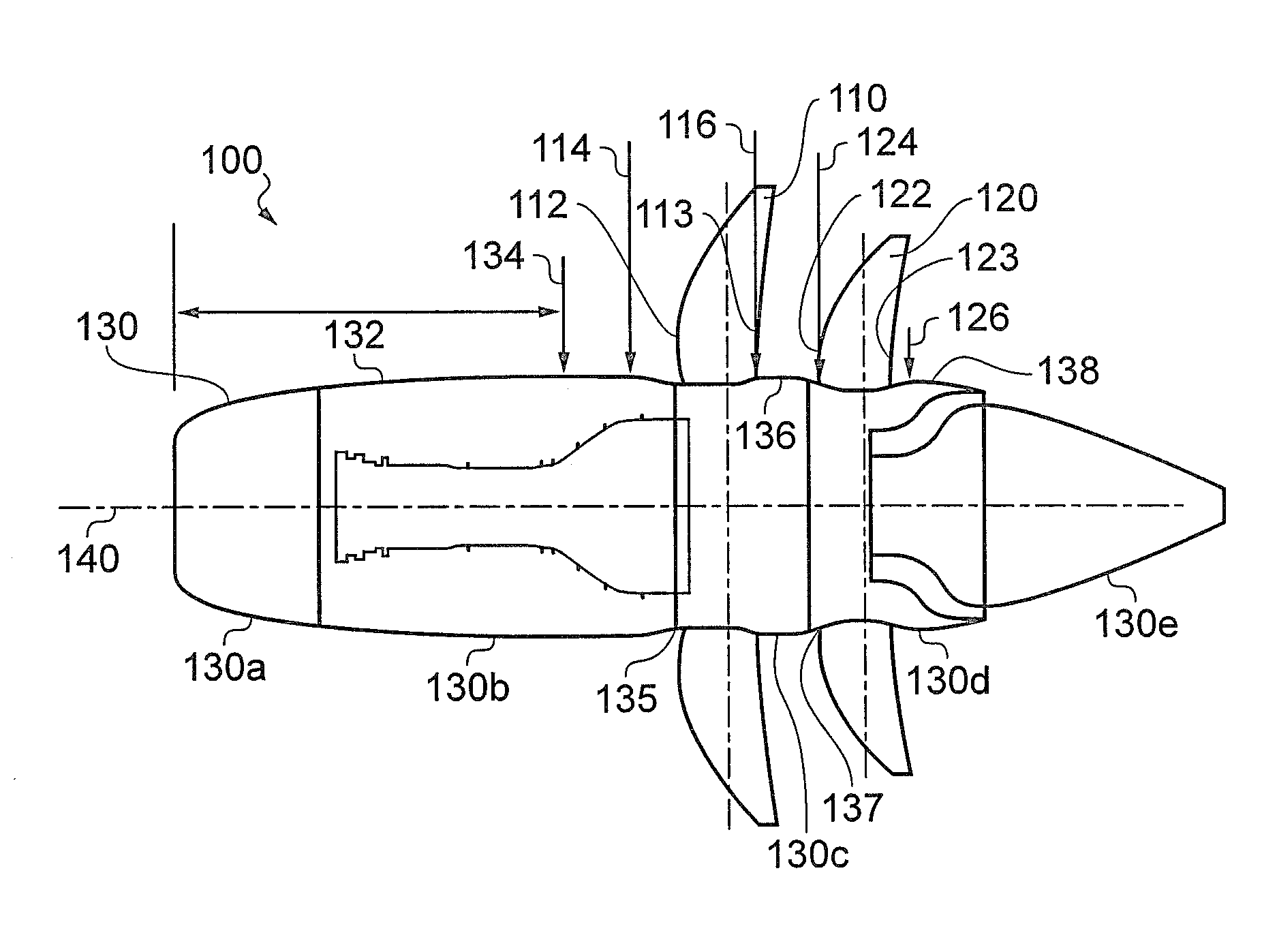
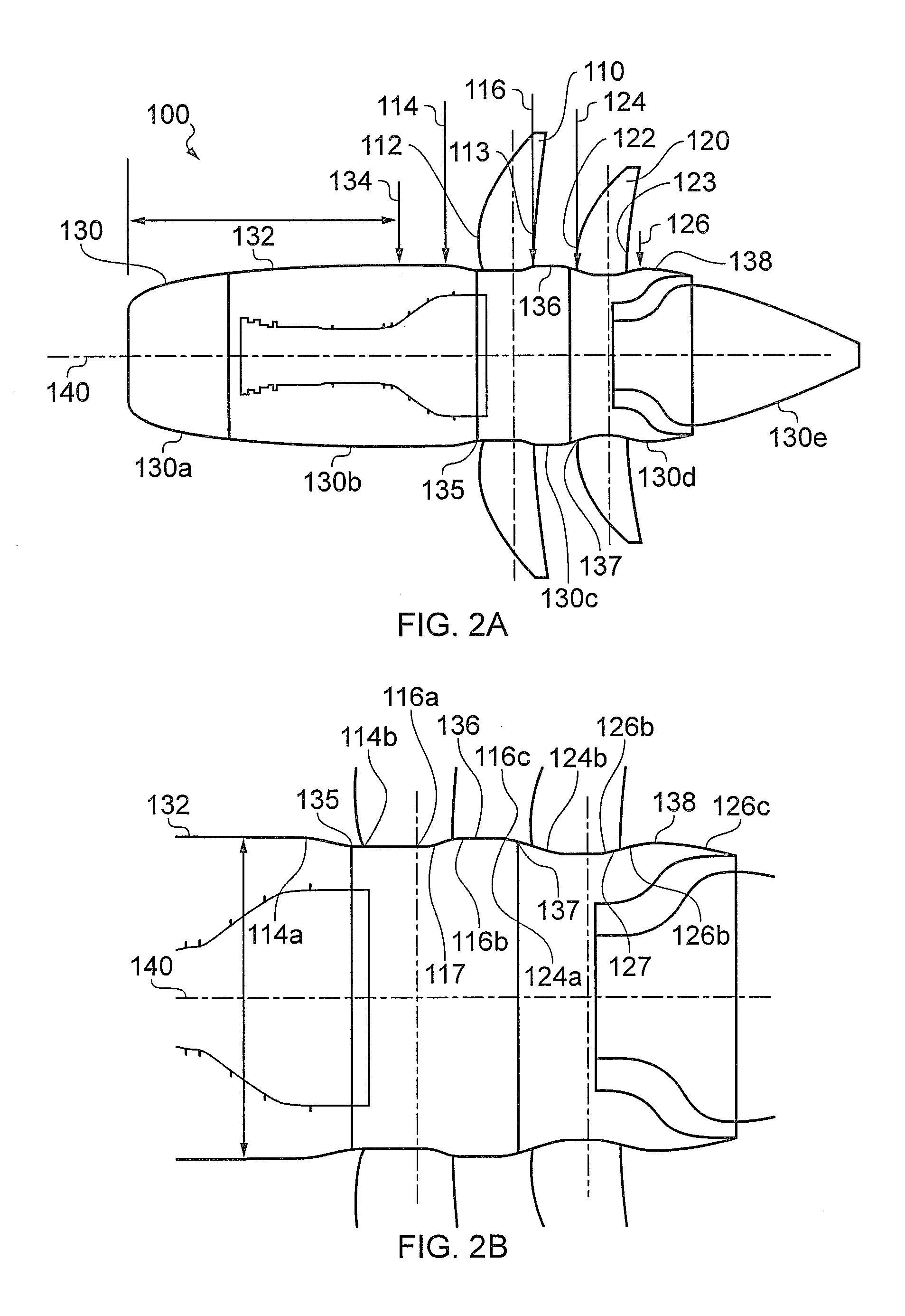
[0033]With reference to FIGS. 2(a) and 2(b), a propfan engine 100, e.g. an unducted turbofan engine, according to an example of the present disclosure, may comprise first and second rotor stages 110, 120 each comprising a plurality of rotors. As shown, the propfan engine may be a pusher type, e.g. the first and second rotor stages 110, 120 may be towards the rear of the engine. However, in an alternative configuration the propfan engine may be a puller type, e.g. the first and second rotor stages may be towards the front of the engine.

[0034]The propfan engine may further comprise an outer wall 130, e.g. nacelle, comprising an outer profile 132. The outer wall 130 may comprise one or more constituent elements. For example, first and second elements 130a, 130b may form a fixed, e.g. non-rotating, portion of the outer wall upstream of the first and second rotors 110, 120. The first element 130a may comprise an inlet cowl and the second element 130b may comprise one or more access doors...


PUM


Abstract

The present disclosure relates to a propfan engine comprising: one or more rotor stages comprising a plurality of rotors; and an outer wall comprising an outer profile, at least a portion of the outer profile defining a substantially circular cross-section, wherein the diameter of the substantially circular cross-section increases in the direction of flow over the outer wall and downstream of a leading edge of the rotors, and the diameter increases at substantially all points defining the circumference of the substantially circular cross-section.

Description

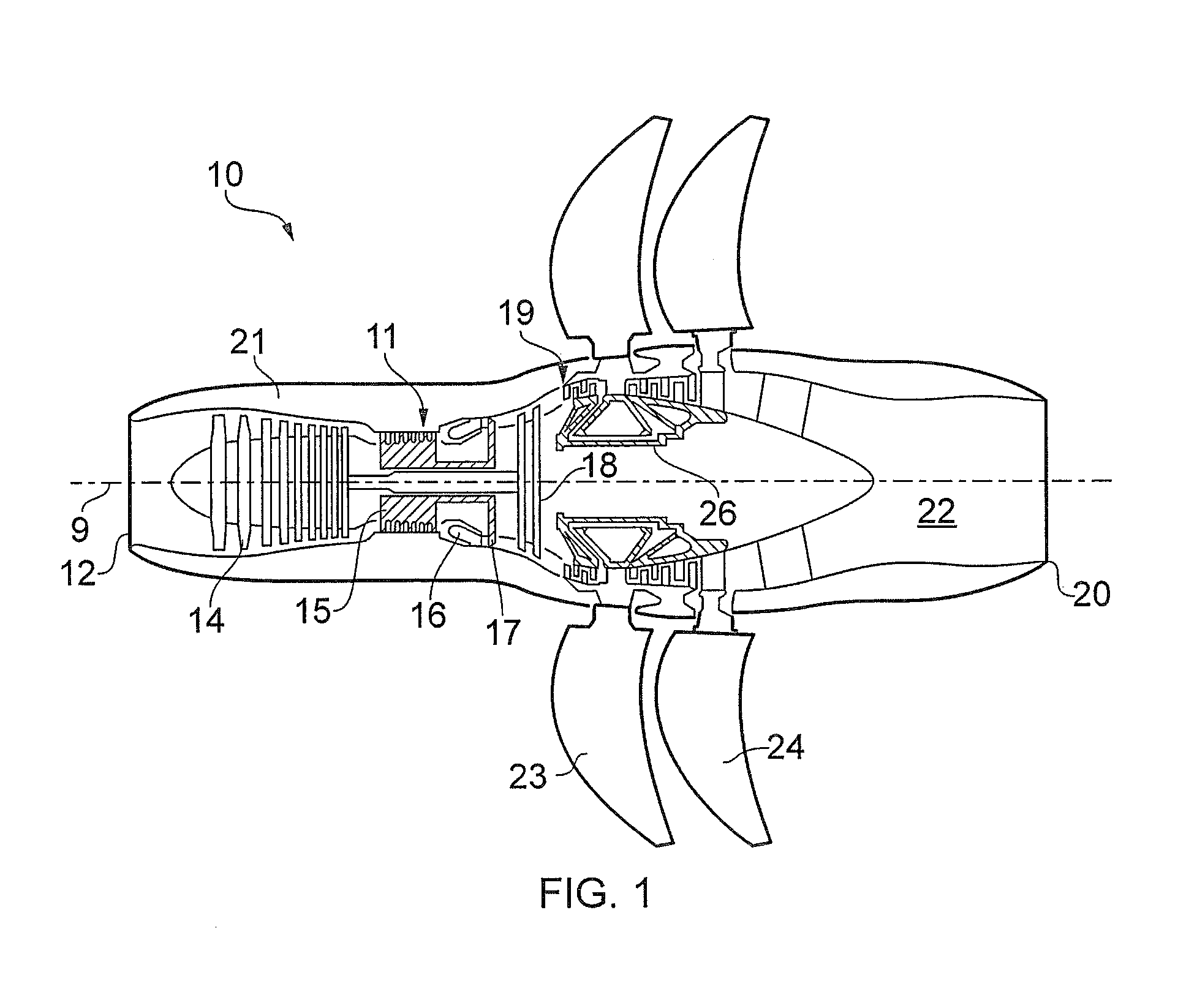
[0001]The present disclosure relates to a propfan engine and particularly but not exclusively relates to a propfan engine with a contoured outer casing.BACKGROUND[0002]Referring to FIG. 1, a conventional twin-spooled, contra-rotating propeller gas turbine engine, e.g. a propfan engine, is generally indicated at 10 and has a principal rotational axis 9. The term “propfan” will be understood by the skilled person to refer to a gas turbine engine having an open rotor, i.e. having a rotor comprising blades that are not surrounded by a nacelle. The engine 10 comprises a core engine 11 having, in axial flow series, an air intake 12, a low pressure compressor 14, a high-pressure compressor 15, combustion equipment 16, a high-pressure turbine 17, a low pressure turbine 18, a free power (or low-pressure) turbine 19 and a core exhaust nozzle 20. A nacelle 21 generally surrounds the core engine 11 and defines the intake 12 and nozzle 20 and a core exhaust duct 22. The engine 10 also comprises ...

Claims


Application Information

Patent Timeline
Patent Type & Authority Patents(United States)
IPC IPC(8): F01D5/02B64C11/48B64D27/00B64D29/00F02K3/072
CPCF01D5/022F02K3/072B64C11/48B64D29/00F05D2240/14F05D2250/70Y02T50/671B64D2027/005Y02T50/66F01D5/143F01D5/145F02C3/067F05D2220/325F05D2220/324Y02T50/60
Inventor STRETTON, RICHARD G.HOWARTH, NICHOLAS
Owner ROLLS ROYCE PLC
Learn More