Bendable pole for wire-rope safety fences

a wire-rope safety fence and bendable technology, applied in the field of bendable poles for wire-rope safety fences, can solve the problems of major drawbacks of wire-rope poles, major injuries, and wire-ropes that are not suitable for collisions with motorcycles

Inactive Publication Date: 2015-03-10
ARJEPOLE SYST
View PDF4 Cites 3 Cited by
  • Summary
  • Abstract
  • Description
  • Claims
  • Application Information

AI Technical Summary

Benefits of technology

[0007]The main purpose of the present invention is to significantly reduce the above mentioned disadvantages and drawbacks. Another purpose of the present patent application is to provide a device which preferably is more cost effective to install and maintain than previously known designs. These purposes are achieved with the aid of a design in accordance with the claims.

Problems solved by technology

Today's wire poles have major drawbacks.
First, the wire poles have such stability in the vehicle's direction of travel that major injury occurs, especially in connection with the collision of vehicles such as motorcycles.
Today's wire-rope is not suitable for collision with motorcycles.
In a collision between a motorcyclist and a wire-rope safety fence the motorcyclist usually receive serious bodily harm.
It is not uncommon for today's wire poles to cause so great bodily harm that not even a first-aid relief effort will be able to prevent the heavy bleeding caused by a collision with current existing wire poles.
A further problem with existing wire poles is that they also cause great material damage, which means high repair costs.
Today's wire poles cause in certain situations such great damage to vehicles such as cars that they must be scrapped and taken out of service, which results in subsequently high costs for individuals and insurance companies.
A yet further problem with existing wire poles is that their construction means that they are largely destroyed (becomes unusable) after a collision and must be replaced with new poles.
The consequence of replacing the poles is high material and labor costs.
In addition to this there is always great risk of injury for roadwork personnel during these repairs that have to be carried out in traffic, where motorists often do not respect the reduced speed limits.

Method used


Image

  • Bendable pole for wire-rope safety fences
  • Bendable pole for wire-rope safety fences
  • Bendable pole for wire-rope safety fences

Examples


Embodiment Construction

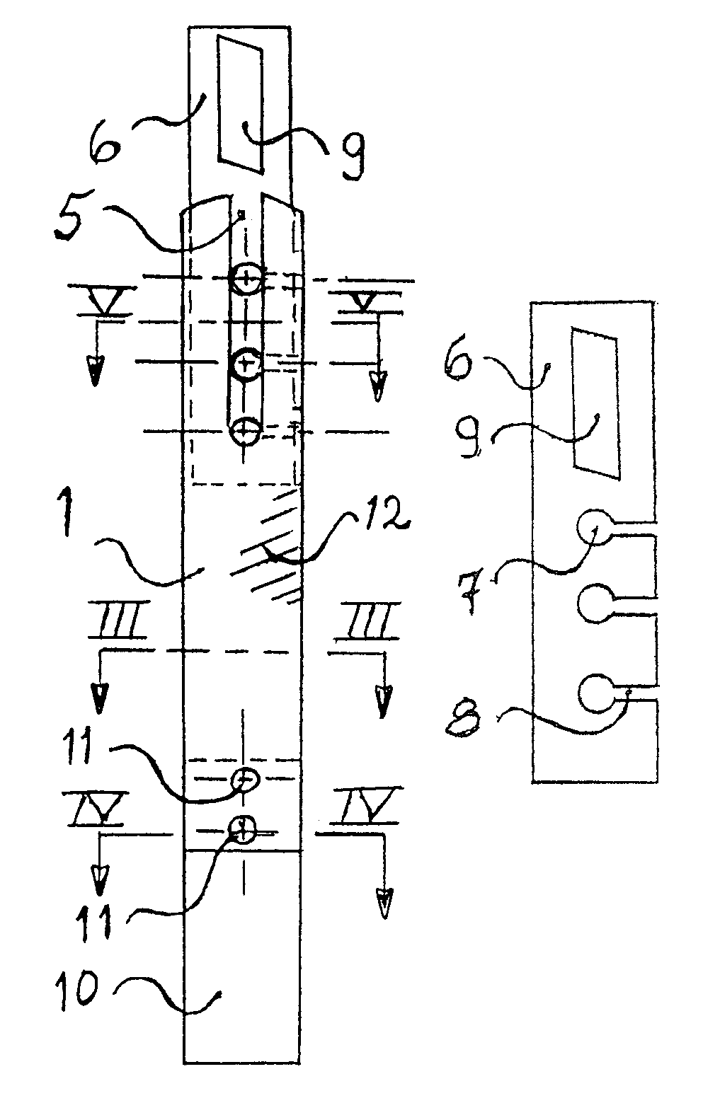
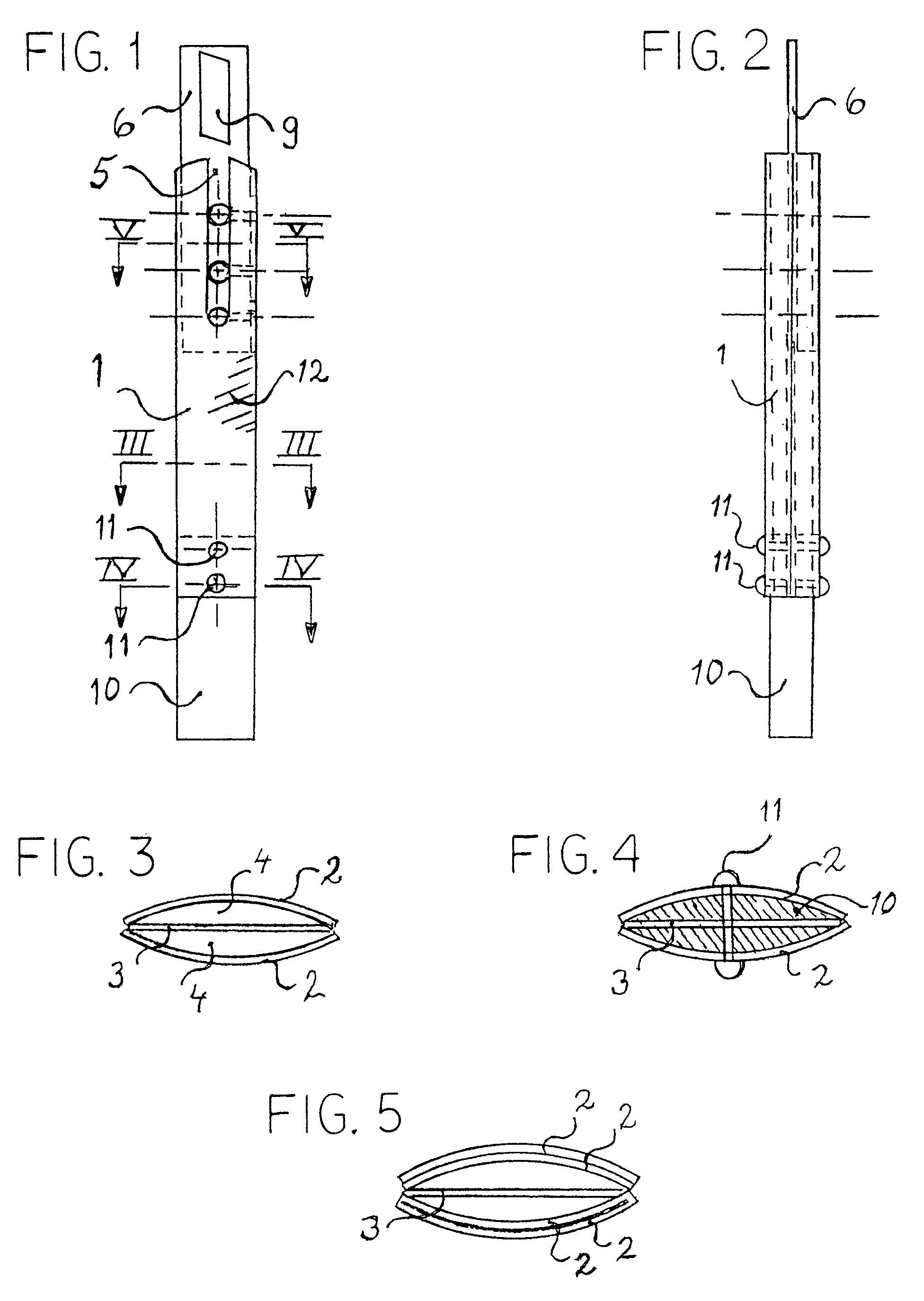
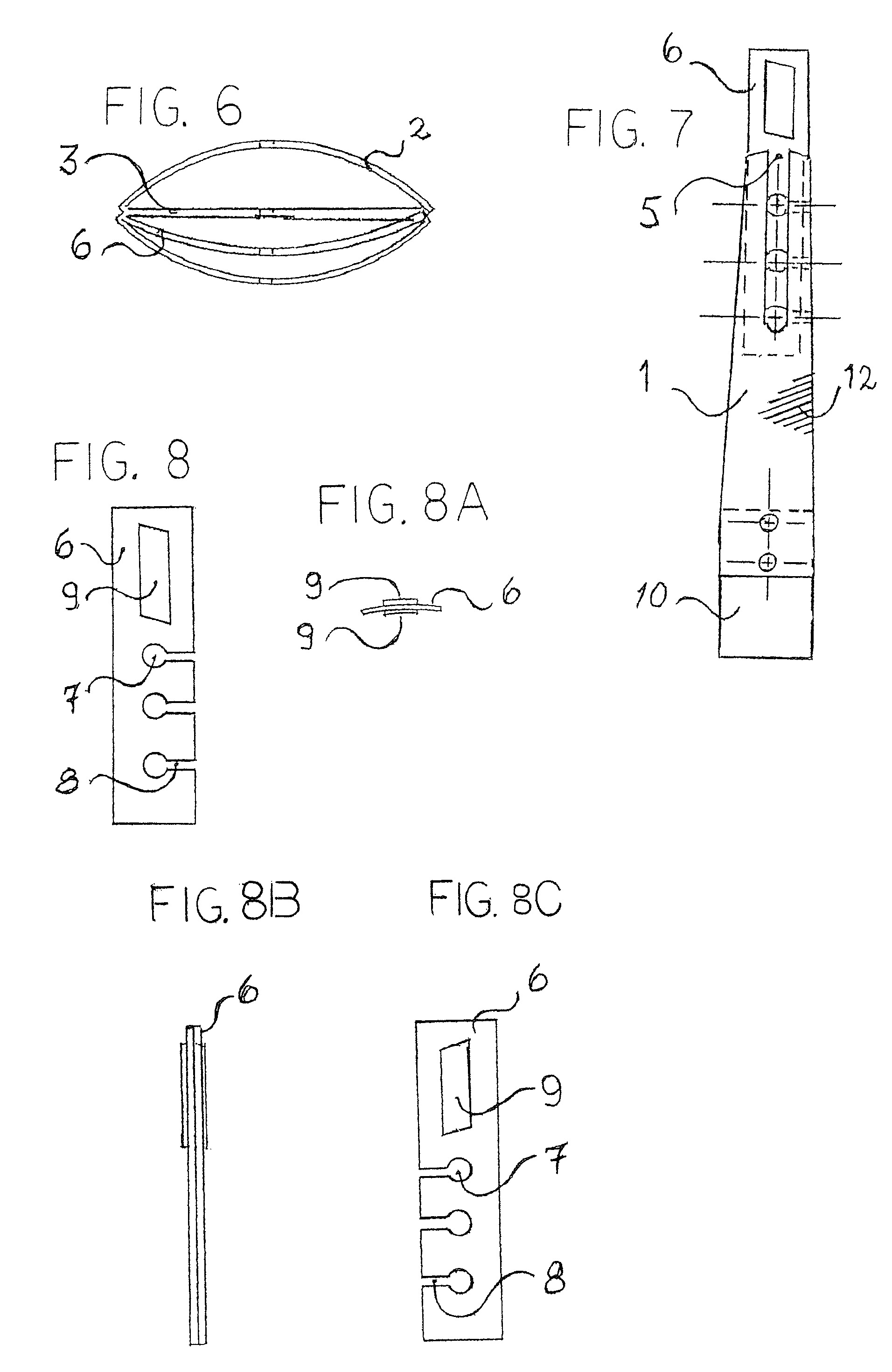
[0024]Referring to the figures, a bendable wire pole 1 in accordance with the present patent application is shown. The unique feature of the present wire pole 1 is that it is bendable in the direction of travel but at the same time also has good lateral and horizontal stability.

[0025]The bendable wire pole 1 includes at least two or more elongated curved-shaped pole sections 2 with at least one intermediate pole section 3. The elongated curved-shaped pole sections 2 form at least one interior cavity (compartment, space) 4

[0026]The intermediate pole section 3 is preferably of a flat design. The pole sections 2 and 3 have essentially the same width. The first elongated curved-shaped pole section's 2 and the intermediate pole section's 3 side edges coincide with each other.

[0027]All sections 2 and 3 are in their upper part equipped with a groove (slot) 5 in the sections' longitudinal direction in which steel wires are designed to be inserted from above during their assembly. The wires ...


PUM


Abstract

Bendable wire pole (1) intended to fixate the wires in a wire-rope safety fence, comprising at least two curved elongated pole sections (2) connected to each other so that at least an intermediate cavity (4) is formed between the sections (2), whose sections (2) are held together by at least one cohesive body (12). The unique feature of the present bendable wire pole (1) is that it includes at least one intermediate elongated pole section (3) positioned between the curved sections (2), whose sections (2) and (3) in their upper are provided with at least one groove (5) in which wires are designed to be inserted. The pole (1) further comprises at least one spacer unit (6), intended to be connected to the wires and the pole (1), with which the wires are positioned in the vertical and horizontal directions relative to the pole (1).

Description

FIELD OF THE INVENTION[0001]The present invention concerns a bendable pole for wire-rope safety fences, in accordance with the claims.TECHNICAL BACKGROUND AND PRIOR ART[0002]Today, wire-rope safety fences, which are usually located between traffic lanes, are used to separate traffic traveling in opposite directions which keeps vehicles from colliding with each other. The wire-rope safety fence prevents oncoming traffic from crossing over into their opposite lanes and thus prevents vehicles from colliding with each other. Wire-rope safety fences are also used as shoulder side wire rope, placed at the road's shoulder to prevent traffic from running of the roadway.[0003]Wire-rope safety fences use poles to hold up and fixate the wire-rope safety fence in relation to the roadway. Today's wire poles have major drawbacks. First, the wire poles have such stability in the vehicle's direction of travel that major injury occurs, especially in connection with the collision of vehicles such as ...

Claims


Application Information

Patent Timeline
Patent Type & Authority Patents(United States)
IPC IPC(8): E01F15/00E01F15/06
CPCE01F15/06
Inventor AKERSTROM, BERNDT
Owner ARJEPOLE SYST
Why Eureka
Try Eureka