Wedge-type drop-in anchor assembly

a drop-in anchor and assembly technology, applied in the field of anchors, can solve the problems of reducing the wedging of the distal ends against the hole walls, collapsing or bending, and reducing the wedging of the distal ends

Inactive Publication Date: 2015-03-10
MECHANICAL PLASTICS CORP
View PDF35 Cites 19 Cited by
  • Summary
  • Abstract
  • Description
  • Claims
  • Application Information

AI Technical Summary

Benefits of technology

[0027]a drop-in anchor that is highly reliable and safe in use;
[0028]a drop-in anchor that is not only convenient and easy to use but also is economical and relatively easy to fabricate;
[0029]a drop-in anchor that has pull-out resistance characteristics that are maintained for a long period of time for long service over years, and which are stable within the concrete substrates or substructures even though there are changes in the condition of the concrete external environmental conditions;

Problems solved by technology

A limitation of using protrusions resulting from dimpling is that under sufficient radially compressive forces resulting from extreme pull-out forces following setting, the resultant squeezing of distal portions of the clip could result in a collapsing of the dimpling or protrusions, causing in other words flattening, with resultant tendency to reduce the wedged impingement of the distal ends against the hole walls.
That is, the grooves, threads, or teeth portions of the clip could result in a collapsing or bending over, with resultant tendency to reduce the wedging of the distal ends against the hole walls.
Therefore, the challenge in the art remains to provide an anchor with a clip having portions that are wedged into a locking arrangement within the anchor hole without inherent tendency to reduce the wedged impingement of the distal ends against the hole walls in the event of extreme pullout forces, and are capable of maintaining reliable securement even in the event that the anchor is located in a hole in cracked concrete or under conditions in which the installation may be under cracked concrete specifications.
The challenge in the art continues to be the provision of an anchor with a clip, where the anchor is capable of meeting cracked concrete testing specifications.

Method used


Image

  • Wedge-type drop-in anchor assembly
  • Wedge-type drop-in anchor assembly
  • Wedge-type drop-in anchor assembly

Examples


Embodiment Construction

[0064]Referring to the drawings, an embodiment of anchor assembly of the invention is generally designated A. For convenience, the anchor assembly may be referred to, throughout this document, as an anchor. It is a hybrid, in the sense that it is a hybrid drop-in anchor provided with an anchoring sleeve.

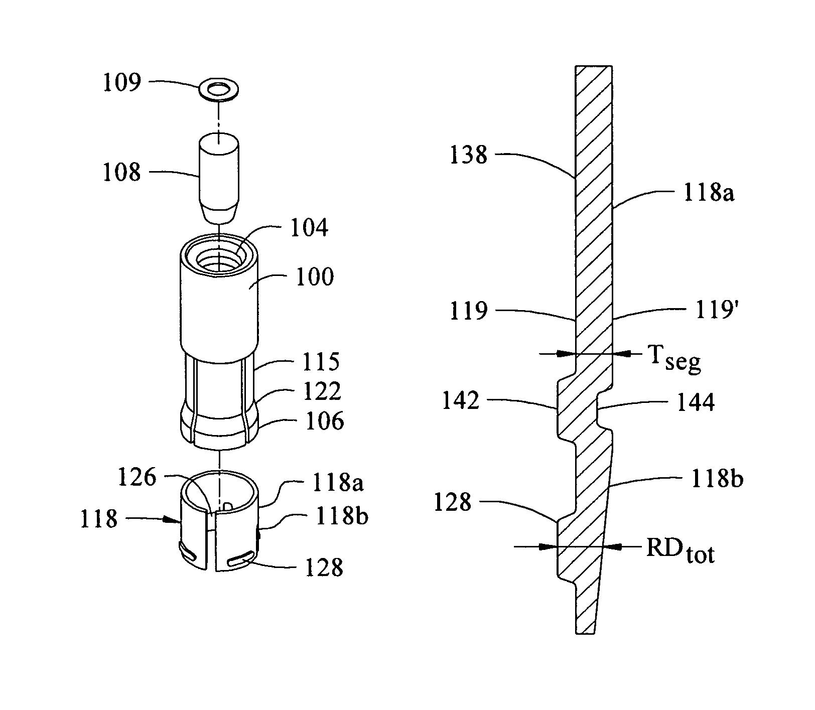
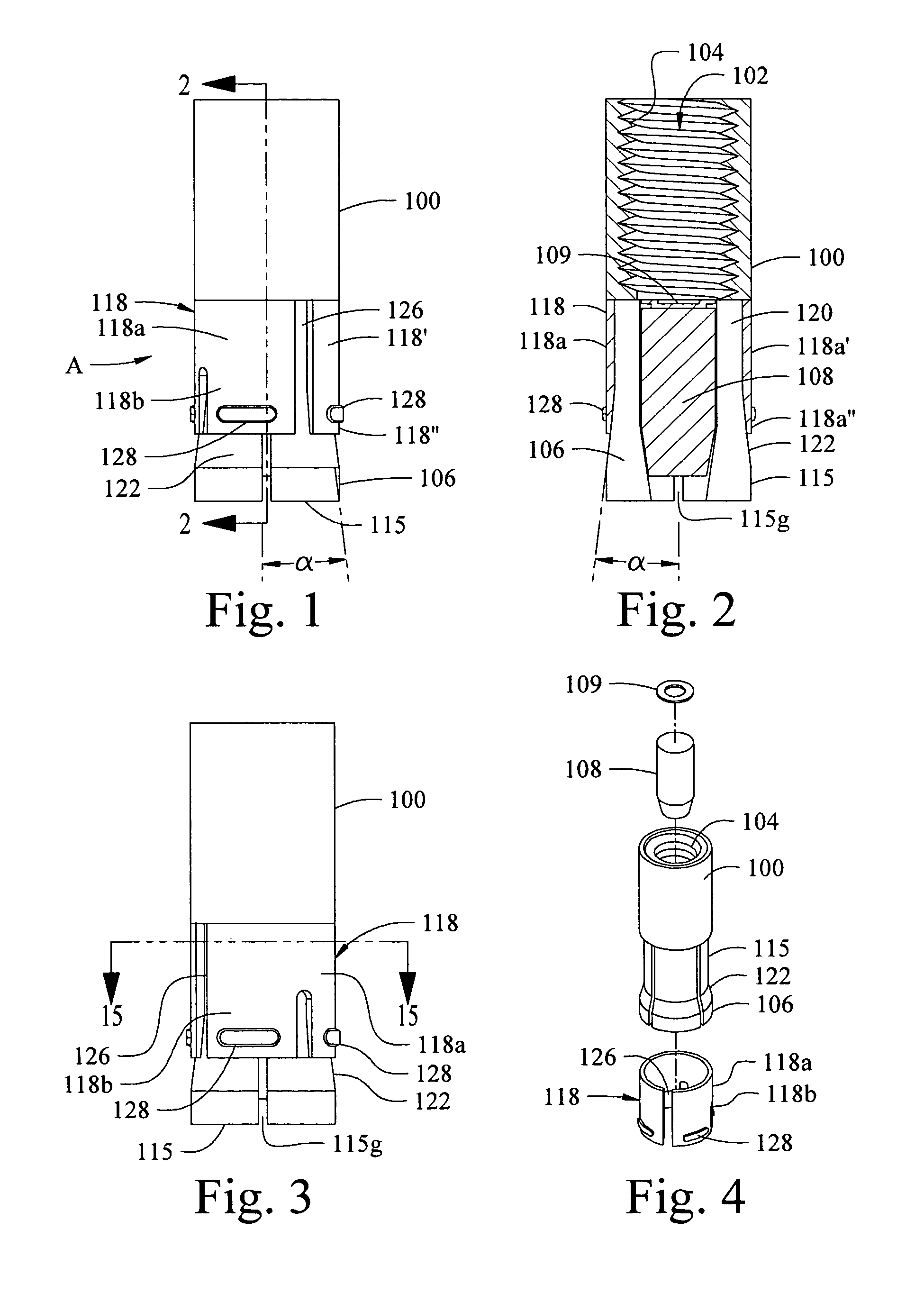
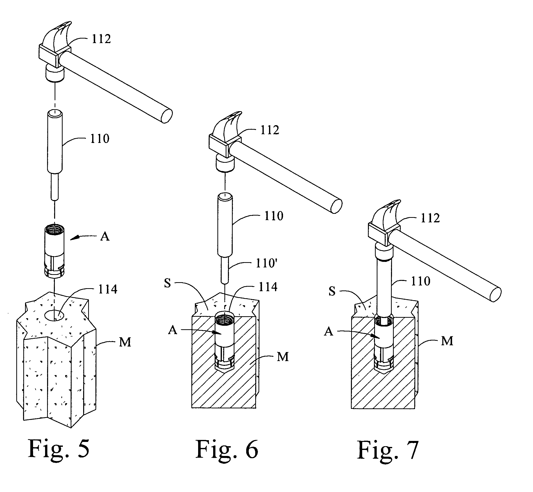
[0065]With reference initially to FIGS. 1-4, the general anchor features are first considered. The anchor has a body 100 that has a through bore 102 having internal threading 104. A split base region 106 has inserted into its central bore a tapered approximately bullet- or conical-shaped setting plug 108, held in place during shipment and storage by a thin wafer 109, as of resilient synthetic material. The plug is capable of being driven baseward by setting tool 110 (FIG. 5) as by a hammer 112 for preliminary setting when the anchor is inserted, base end first, into a borehole. Such a hole is shown at 114 in FIG. 5 and in other figures. A threaded male member such as a bolt 116, or a...


PUM


Abstract

A hybrid drop-in anchor with an expansion sleeve, a split base region of an anchor body and a setting plug. The sleeve surrounds an annular body recess of the body, with a clip portion extending around an annular recess. Clip segments extend from the arcuate portion, each having a proximal portion with an original thickness and a distal portion having at least one projection, extending therefrom. The projection extends from the outer surface without corresponding cavity on an inner surface, with a projection of total thickness greater than the original thickness. After the setting plug is driven, and the threaded male member is inserted and tightened, pulling movement of the anchor moves the expansion sleeve baseward, such that each segment rides outwardly on the tapered portion, providing radial expansion of the anchor and locking, wedging engagement of each segment projection with wall surfaces with enhanced pull-out resistance.

Description

BACKGROUND[0001]1. Field of the Invention[0002]The presently described invention generally relates to anchors and more particularly to so-called drop-in anchors having expandable wedge-forming elements for securement of the anchors within holes in work surfaces of concrete, masonry, brick or comparable materials. The invention specifically relates to anchors that are capable of meeting cracked concrete testing standards.[0003]2. Background[0004]The terms “borehole” or “bore hole” and “hole for the anchor” and “anchor hole” and “drill hole” and / or simply “hole”, as used in this description, are simply convenient terms, as a hole for such an anchor may be formed in ways other than drilling, boring or punching.[0005]The name “drop-in anchor” is a term of art for a general class of anchors that are especially convenient to use. The term is not intended to limit use of the anchor, which anchor is not necessarily “dropped” or otherwise pressed in place; and such anchors may be used in man...

Claims


Application Information

Patent Timeline
Patent Type & Authority Patents(United States)
IPC IPC(8): F16B13/06
CPCF16B13/063
Inventor RICKETTS, MICHAEL J.
Owner MECHANICAL PLASTICS CORP
Why Eureka
Try Eureka