
Cable for transmitting signals

a technology for transmitting signals and cables, applied in the direction of coupling device connections, correct coupling prevention, securing/insulating coupling contact members, etc., can solve the problems of limited transmittable data rates and relatively many additional parts required to produce such cables, and achieve the effect of high data rates and relatively low production costs

Active Publication Date: 2015-03-10
MD ELEKTRONIK
View PDF15 Cites 10 Cited by
  • Summary
  • Abstract
  • Description
  • Claims
  • Application Information

AI Technical Summary

Benefits of technology

[0005]Example embodiments of the present invention provide a cable which allows a high-quality signal transmission at high data rates and yet is able to be manufactured at relatively low production cost.
[0012]It is possible to produce the body in one piece from an insulating material, e.g., by an injection-molding method, and the second latching element may be arranged as an integral component of the body.

Problems solved by technology

One of the disadvantages of the configuration described in U.S. Patent Application Publication No. 2003 / 0199205 is that the transmittable data rates are limited and that relatively many additional parts are required to produce such a cable.

Method used


Image

  • Cable for transmitting signals
  • Cable for transmitting signals
  • Cable for transmitting signals

Examples


Embodiment Construction

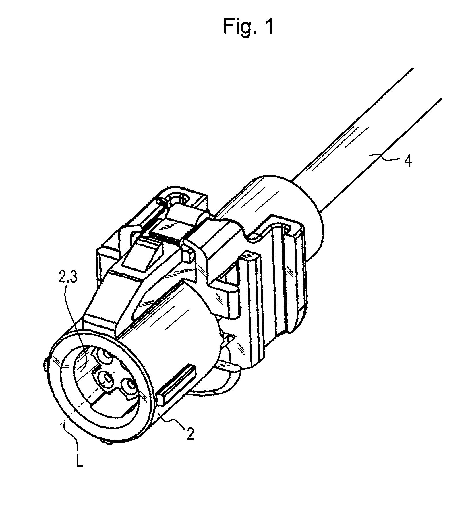
[0032]FIG. 1 illustrates a cable for the transmission of signals, to be installed in a vehicle, for example. Video images from a camera, for example, are able to be transmitted to an onboard computer with the aid of the signals, for which purpose Ethernet technology may be used, for instance. Via a coupler element, the end of the cable is able to be connected in separable manner to a corresponding mating element of another component, such as an element of an onboard electronics system, in the sense of a plug connection.

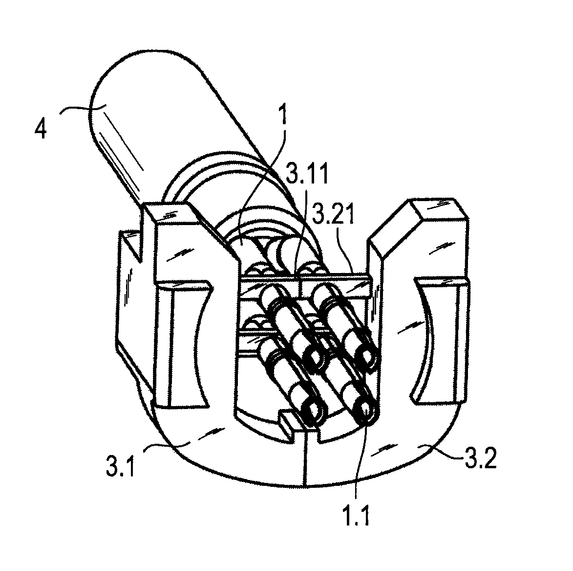
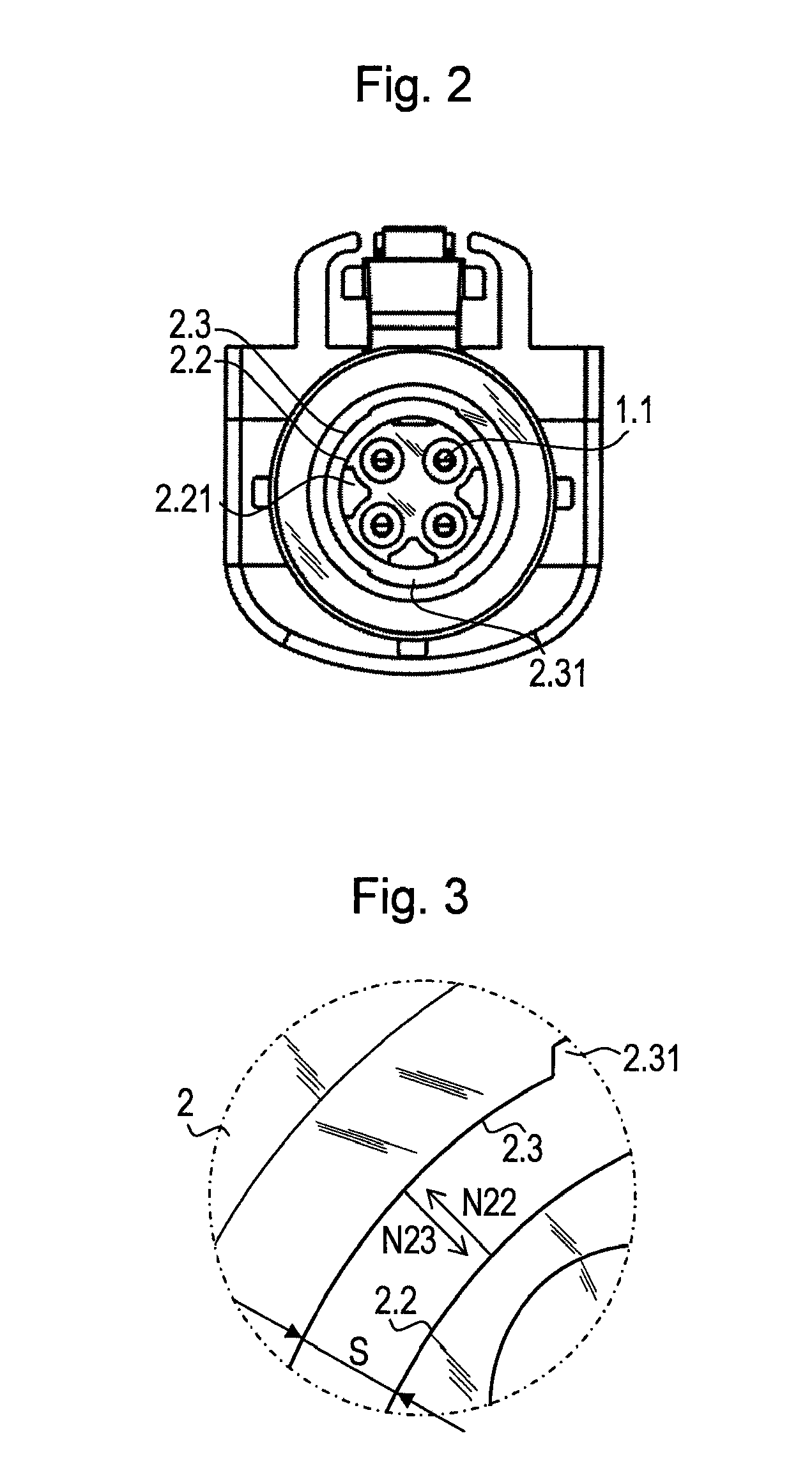
[0033]In the exemplary embodiment illustrated, the cable has four leads 1 (see FIGS. 4 through 8), which are surrounded by an electrically insulating sheath 4 toward the outside. In addition, each of the four leads 1, as illustrated in FIG. 5, is provided with insulation around an internal conductor, which is removed only in the end region of each lead 1. In the end region, stripped of the insulation, the internal conductors are contacted by an end piece 1.1 in each c...


PUM


Abstract

A cable for the transmission of signals, includes a plurality of leads, on whose inner conductors an electrically conductive end piece is affixed. At least one of the end pieces includes a first latching element. The cable includes a coupler element, and the coupler element has a body having a longitudinal axis. In addition, the body has parallel feed-throughs, electrically insulated from each other, to accommodate the end pieces. At least one of the feed-throughs includes a second latching element. The end piece is inserted into the feed-through such that the first latching element locks into place with the second latching element. The body furthermore has a first surface and a second surface to guide a mating piece of the coupler element, the first surface having a radially outwardly directed normal vector, and the second surface having a radially inwardly directed normal vector.

Description

CROSS-REFERENCE TO RELATED APPLICATIONS[0001]The present application claims priority to Application No. 12 000 997.2, filed in the European Patent Office on Feb. 16, 2012, which is expressly incorporated herein in its entirety by reference thereto.FIELD OF THE INVENTION[0002]The present invention relates to a preassembled cable, for example, a cable including a coupler element or a plug connector, for the transmission of signals.BACKGROUND INFORMATION[0003]Numerous cables are used in motor vehicles or aircrafts, for example, and are often required in large numbers. A simple design and an uncomplicated preassembly are of great importance for the cost-effective provision of corresponding cables. Cables of this type must be manufactured such that they allow the transmission of signals at high data rates as required in a high-quality transmission of video signals, for example.[0004]A multi-lead shielded cable, which includes a coupler element, is described, for example, in U.S. Patent A...

Claims


Application Information

Patent Timeline
Patent Type & Authority Patents(United States)
IPC IPC(8): H01R13/64H01R13/42H01R13/436H01R13/645H01R13/646H01R24/40
CPCH01R13/42H01R13/4367H01R24/40H01R13/6456H01R13/646
Inventor FRIESE, NORBERTHUBER, MARTIN
Owner MD ELEKTRONIK
Learn More