
Electro-optical switching fabric systems and methods

a switching fabric and optical technology, applied in the field of electrical switching fabric systems and methods, can solve the problems of multi-chassis routers and electrical switches, interconnect scaling problems, and increasing difficulty in providing adequate electrical switching capability to support all possible server-to-server communication patterns at full bandwidth across a large data center

Active Publication Date: 2015-03-17
CIENA
View PDF3 Cites 17 Cited by
  • Summary
  • Abstract
  • Description
  • Claims
  • Application Information

AI Technical Summary

Benefits of technology

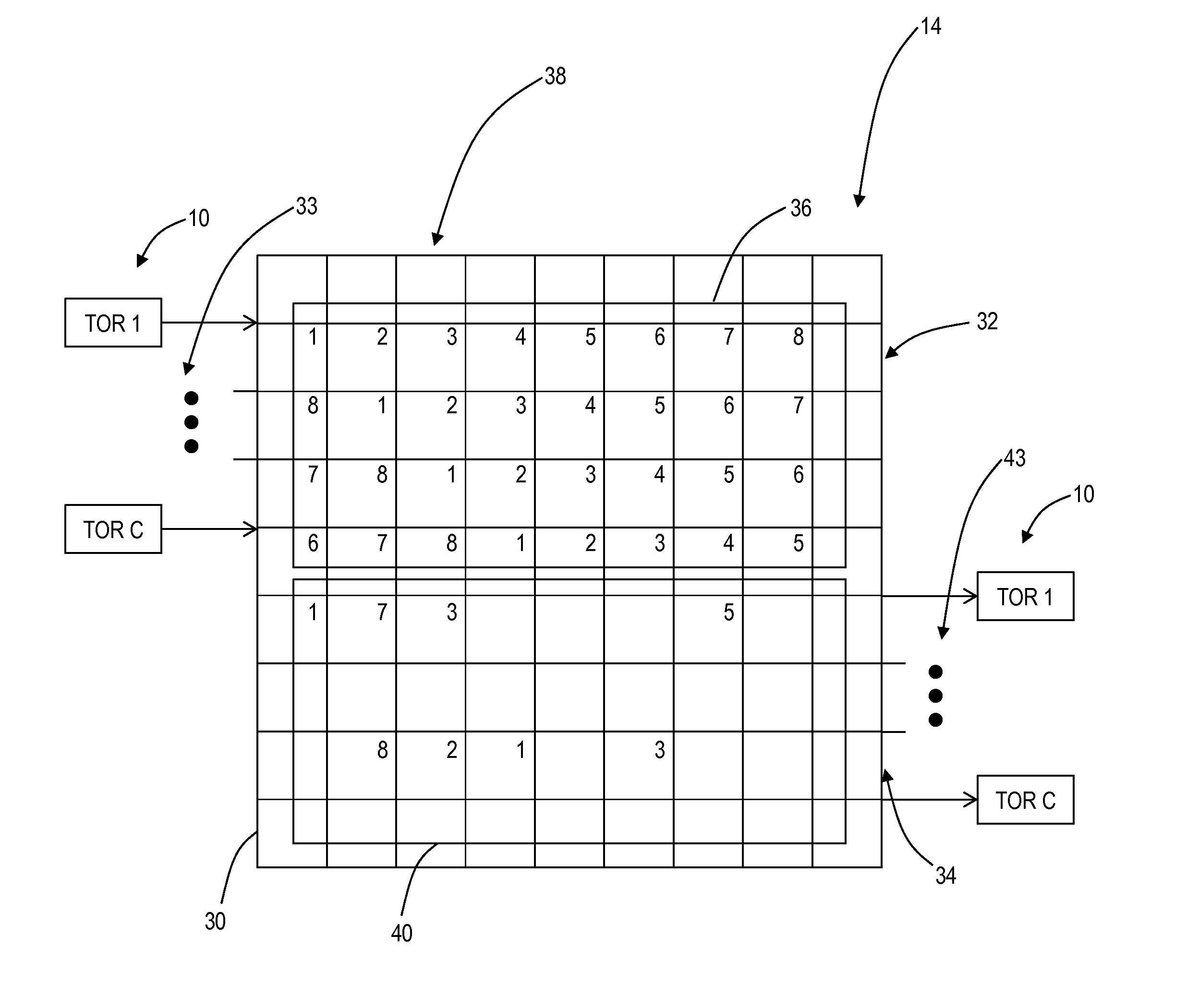
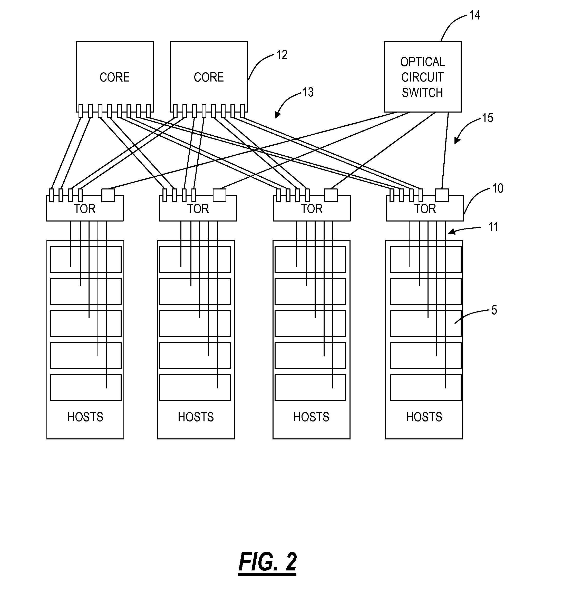
The present patent provides an optical switch fabric that includes a centralized optical cross-connect switch and edge switches. The switch fabric has wavelength-selective drop optical switches and controllable optical switches that can direct wavelengths to different locations. The switch fabric can be reconfigurable and can be used in data centers and other optical systems. The technical effects of the patent include improved optical switch performance, increased flexibility, and improved network efficiency.

Problems solved by technology

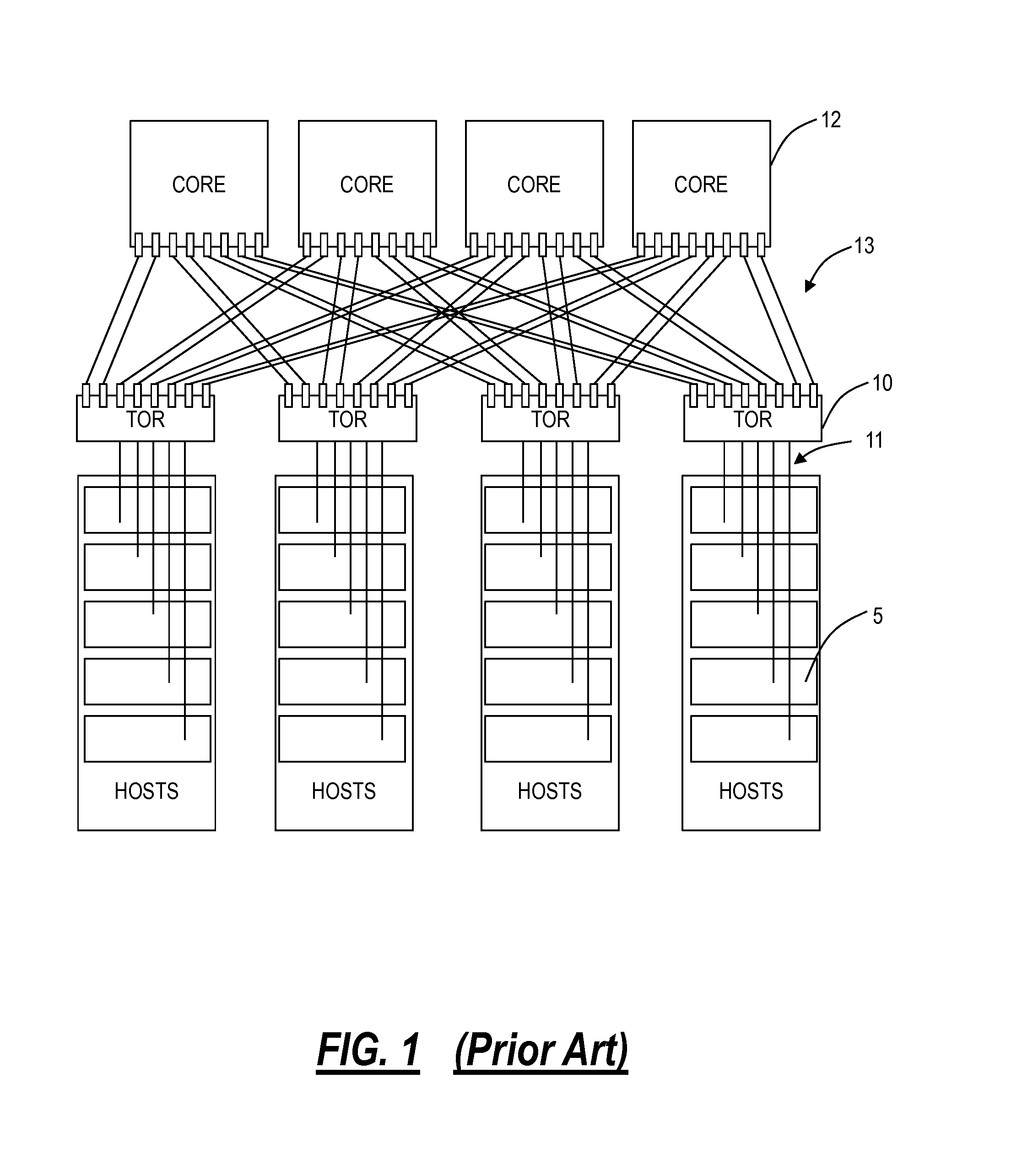
As server bandwidth grows from 10 Gbps to 40 Gbps and beyond, it becomes increasingly difficult to provide adequate electrical switching capability to support all possible server-to-server communication patterns at full bandwidth across a large data center.
A similar interconnect scaling problem exists in multi-chassis routers and electrical switches.
That is, data center applications are an exemplary embodiment and generally this interconnect scaling problem can exist with any generalized multi-chassis routers and electrical switches.
However, projected network junction bandwidth is anticipated to require multi-chassis switching solutions to reach the required scale, and, in such systems, the multi-chassis interconnects present significant challenges in terms of size, cost, and power dissipation.
Additional layers (typically aggregation switches) may be added if increased capacity is required, but at a substantial increase in overall complexity, cost, and power consumption.
Thus, the scale of modern data centers is such that managing TOR-to-core uplinks becomes very difficult.
The sheer number of required interconnect cables leads to management and cost problems.
The optical cables become a jumbled mess.

Method used


Image

  • Electro-optical switching fabric systems and methods
  • Electro-optical switching fabric systems and methods
  • Electro-optical switching fabric systems and methods

Examples


example 1

4 Rack TORs, 3 Waves, Full 1:1 Mesh (Excluding Loopback)

[0043]

c1c2c3c4 InpRow 1:1320 InpRow 2:0213 InpRow 3:2031 InpRow 4:3102OutRow 1:2103OutRow 2:3021OutRow 3:0312OutRow 4:1230

It is interesting to note that above configuration has 3 wavelengths for interconnecting 4 nodes (no loopback), but still requires 4 columns.

example 2

4 Rack TORs, 4 Waves, Full 1:1 Mesh (Excluding Loopback) with Demands 1-3 and 2-4 at 2 Waves

[0044]

c1c2c3c4 InpRow 1:2341 InpRow 2:4132 InpRow 3:3214 InpRow 4:1423OutRow 1:3412OutRow 2:1243OutRow 3:4321OutRow 4:2134

example 3

6 Rack TORs, 6 Waves, Full 1:1 Mesh (Excluding Loopback)

[0045]

c1c2c3c4c5c6InpRow 1:125430InpRow 2:631240InpRow 3:514603InpRow 4:346510InpRow 5:253160InpRow 6:062351OutRow 1:642103OutRow 2:563410OutRow 3:056231OutRow 4:215340OutRow 5:321650OutRow 6:134560

[0046]Thus a matrix of controllable switches on the horizontal waveguides serves to simultaneously demux input wavelengths and rearrangeably mux them onto vertical waveguides, achieving a fully non-blocking interconnect. The specific association of the data flow with a wavelength can be achieved using wavelength tunable transceivers. However, this is generally optically complex and expensive. A preferred method is to provide this association at the electrical layer in the TOR, keeping optical wavelengths fixed. This allows arbitrary cross-connectivity of wavelengths and achieves the goals of:

1. Support for a large number of wavelengths (at least 40, preferably 128 or more);

2. Support for a large number of rack interconnects (at least...


PUM


Abstract

An optical switch fabric, including: a first set of horizontal optical waveguides receiving a plurality of wavelengths; a plurality of wavelength-selective drop optical switches associated with the first set of horizontal optical waveguides, wherein the plurality of wavelength-selective drop optical switches are each configured to drop a selected wavelength from a horizontal optical waveguide of the first set of horizontal optical waveguides to an associated vertical optical waveguide of a plurality of vertical optical waveguides; and a plurality of controllable optical switches associated with the plurality of vertical optical waveguides, wherein the plurality of controllable optical switches are each configured to direct a selected wavelength from a vertical optical waveguide of the plurality of vertical optical waveguides to a horizontal optical waveguide of a second set of horizontal optical waveguides, and wherein the second set of horizontal optical waveguides output a plurality of wavelengths.

Description

FIELD OF THE DISCLOSURE[0001]The present disclosure describes switching fabric systems and methods, and more particularly, electro-optical switching fabric systems and methods which may be used for the interconnection of switches such as server racks in a data center or the like. Further, the present disclosure describes systems and methods for the interconnection of multi-rack routers and electrical switches such as in a data center or the like. These interconnections are based on a novel optical switch fabric and associated method of operation.BACKGROUND OF THE DISCLOSURE[0002]A small data center may include a modest number of server racks, but a large data center may include 100,000 servers or more. There are typically 20-100 servers in a server rack, meaning that 1,000-5,000 server racks are present in such a large data center. These server racks each typically include an electrical switch interconnecting the servers in the server rack, and interconnecting the servers with other...

Claims


Application Information

Patent Timeline
Patent Type & Authority Patents(United States)
IPC IPC(8): G02B6/26H04B10/27H04J14/02H04Q11/00
CPCH04J14/0212H04B10/271G02B6/26H04Q11/0001H04Q11/0005H04J14/0213H04Q2011/0032H04J14/0257H04Q2011/003G02B6/35
Inventor FRANKEL, MICHAEL Y.GAZIER, MICHAELBERTHOLD, JOSEPH
Owner CIENA
Learn More