
Method and system for broadcasting multimedia message

a multimedia message and broadcasting technology, applied in the field of internet technology, can solve the problems of service failure, lager waste of network bandwidth, and inability to organize and optimize connections between nodes in p2p networks, and achieve the effect of saving bandwidth and processing capacity resources

Active Publication Date: 2015-03-17
PATTINGTON IP LLC
View PDF20 Cites 0 Cited by
  • Summary
  • Abstract
  • Description
  • Claims
  • Application Information

AI Technical Summary

Benefits of technology

This patent describes a method for forwarding messages in a structured P2P network, which ensures that all nodes can receive the messages without using the same network resources as the broadcast source. This results in savings of bandwidth and processing capacity, and also helps to evenly distribute load to the nodes and avoid processing bottlenecks.

Problems solved by technology

However, the unstructured P2P network does not have algorithms for organizing and optimizing the connections between nodes, and locating resources should be performed with the aid of the retrieval server, or should be performed by broadcasting the resource access requests to all known peer nodes.
Compared with the structured P2P network, the main disadvantage of the unstructured P2P network is that the broadcasting flood will cause a lager waste of the network bandwidth.
Furthermore, in the unstructured P2P network, broadcasting requests is a kind of practices with the best effort, which can't ensure that the request can reach the right node, thereby causing a service failure.
However, there is no mechanism for broadcasting multimedia messages in the current peer to peer network.

Method used


Image

  • Method and system for broadcasting multimedia message
  • Method and system for broadcasting multimedia message
  • Method and system for broadcasting multimedia message

Examples


Embodiment Construction

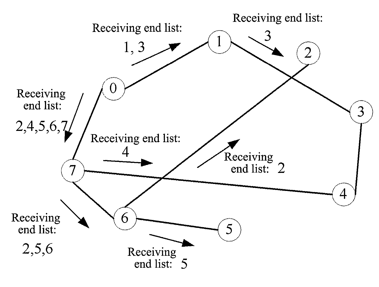
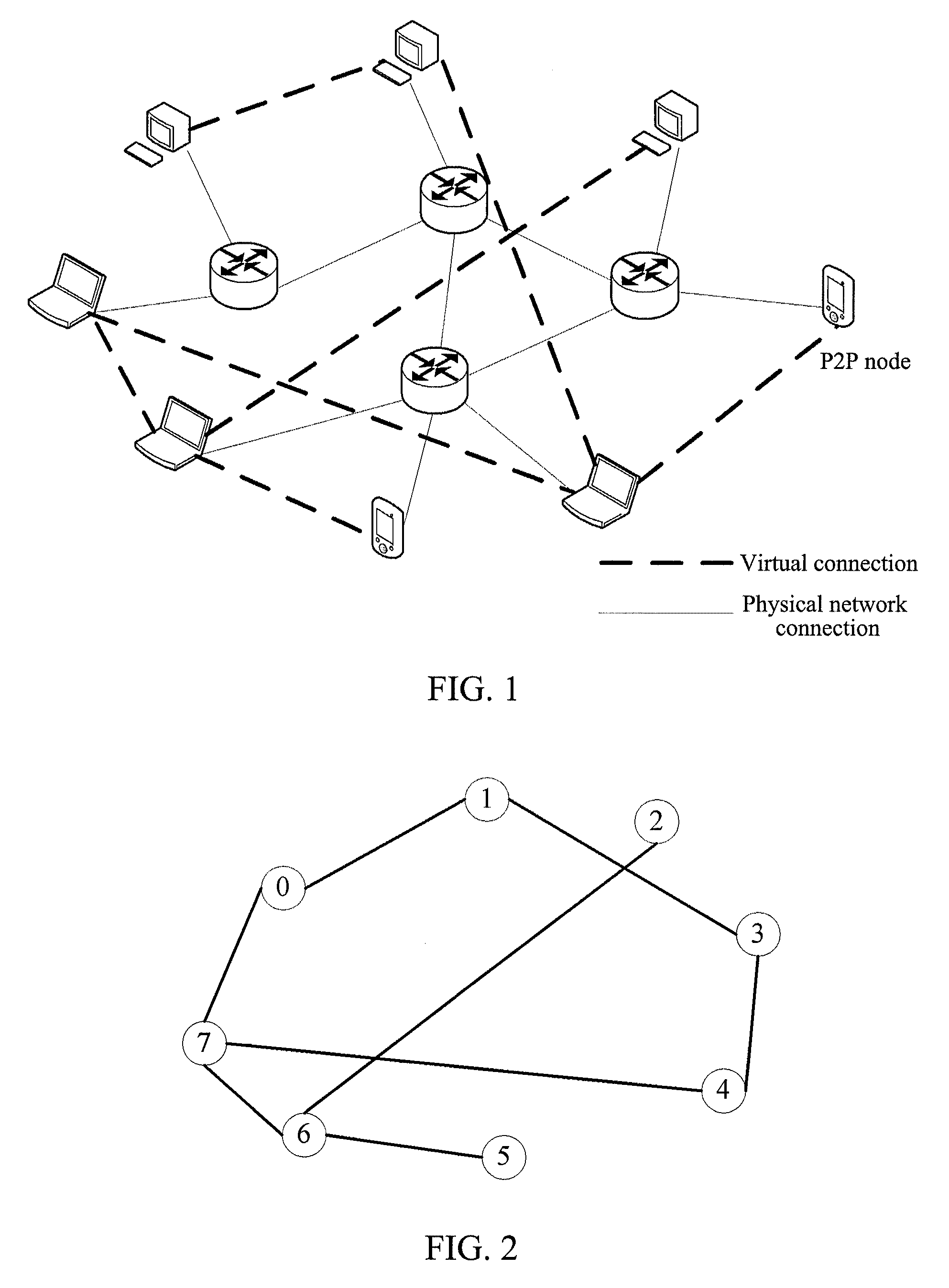
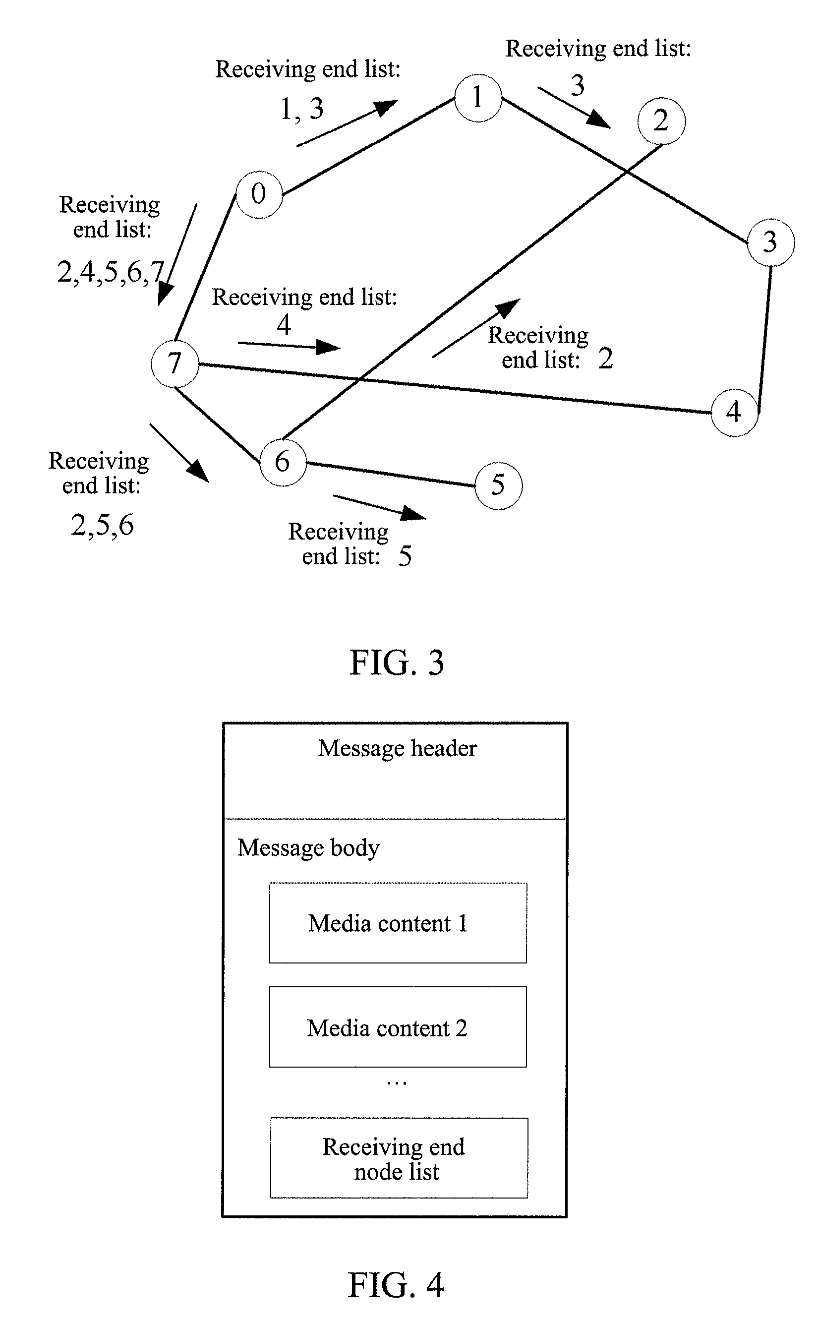
[0049]FIG. 2 is the service network architecture of the multimedia message broadcast service, wherein the peer node can be divided into the broadcast source and the receiving end according to the service definition. As shown in FIG. 2, the broadcast source node 0 is responsible for generating and sending the multimedia message contents, the receiving ends 1˜7 are responsible for receiving and forwarding the multimedia message contents and displaying the multimedia message contents to the users.

[0050]With respect to the network architecture of FIG. 2, the present invention provides a method for broadcasting the multimedia message, which adopts the “relay broadcast” mode to send a broadcast message, that is, the broadcast source node does not send the message to all the receiving end nodes one by one, but send the message to the nodes which have established the virtual connections with the broadcast source node and then these nodes “forwards” the message to other nodes, and so on, unt...


PUM


Abstract

A method and system for broadcasting a multimedia message are disclosed. The method includes: a broadcasting source node packs multimedia content to be broadcasted into a multimedia message, and sends the multimedia message to a reception end node in structural Peer-to-Peer which establishes a virtual connection with the present broadcasting source node; the reception end node receiving the multimedia message forwards the multimedia message to other reception end nodes establishing a virtual connection with the present reception end node. The method and system can save bandwidth and processing capability resources of the whole overlay network, and can make loads be distributed to nodes except the broadcasting source node more evenly to prevent the broadcasting source node from being bottleneck.

Description

CROSS-REFERENCE TO RELATED APPLICATION[0001]This application is the U.S. national phase of PCT Appln. No. PCT / CN2010 / 072789 filed May 14, 2010 which claims priority to Chinese Application No. 200910172962.4 filed Sep. 11, 2009, the disclosures of which are incorporated in their entirety by reference herein.TECHNICAL FIELD[0002]The present invention relates to the field of Internet technology, and more especially, to a method and a system for broadcasting a multimedia message.BACKGROUND OF THE RELATED ART[0003]The Peer-to-Peer (P2P) network is a kind of distributed application architecture, and is mainly composed of a plurality of peer nodes. The peer nodes share a part of their own resources, such as the processing capability and network bandwidth and so on, and provide services for all peer nodes (including themselves) in common. On the service path of the P2P network, there is no server in the traditional sense, and furthermore, the peer nodes can dynamically join in and quit the ...

Claims


Application Information

Patent Timeline
Patent Type & Authority Patents(United States)
IPC IPC(8): G06F15/16H04L12/18H04L12/58H04L29/08
CPCH04L12/1854H04L67/104H04L51/10H04L12/1886H04L12/185
Inventor SHE, KUN
Owner PATTINGTON IP LLC
Learn More