

Bucket lift ring for loader and backhoe buckets
a bucket and bucket lift technology, applied in the field of bucket lift rings for loaders and backhoes, can solve the problems of reducing the service life of the bucket, and requiring a lot of chain to wrap around the bucket, so as to reduce the time, minimize play, and save cost and weight
- Summary
- Abstract
- Description
- Claims
- Application Information
AI Technical Summary
Benefits of technology
Problems solved by technology
Method used
Image

Examples
Embodiment Construction
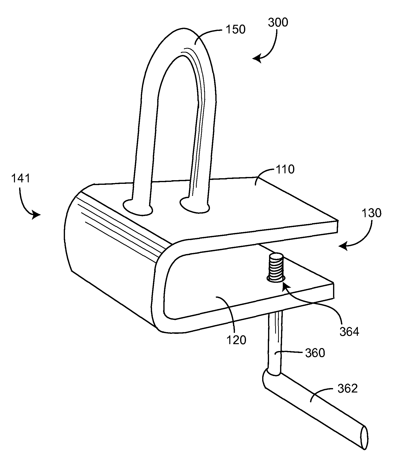
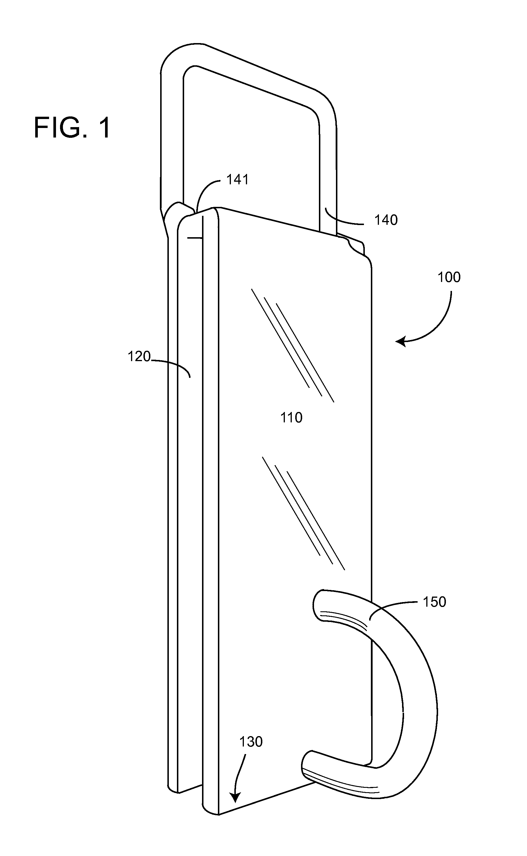
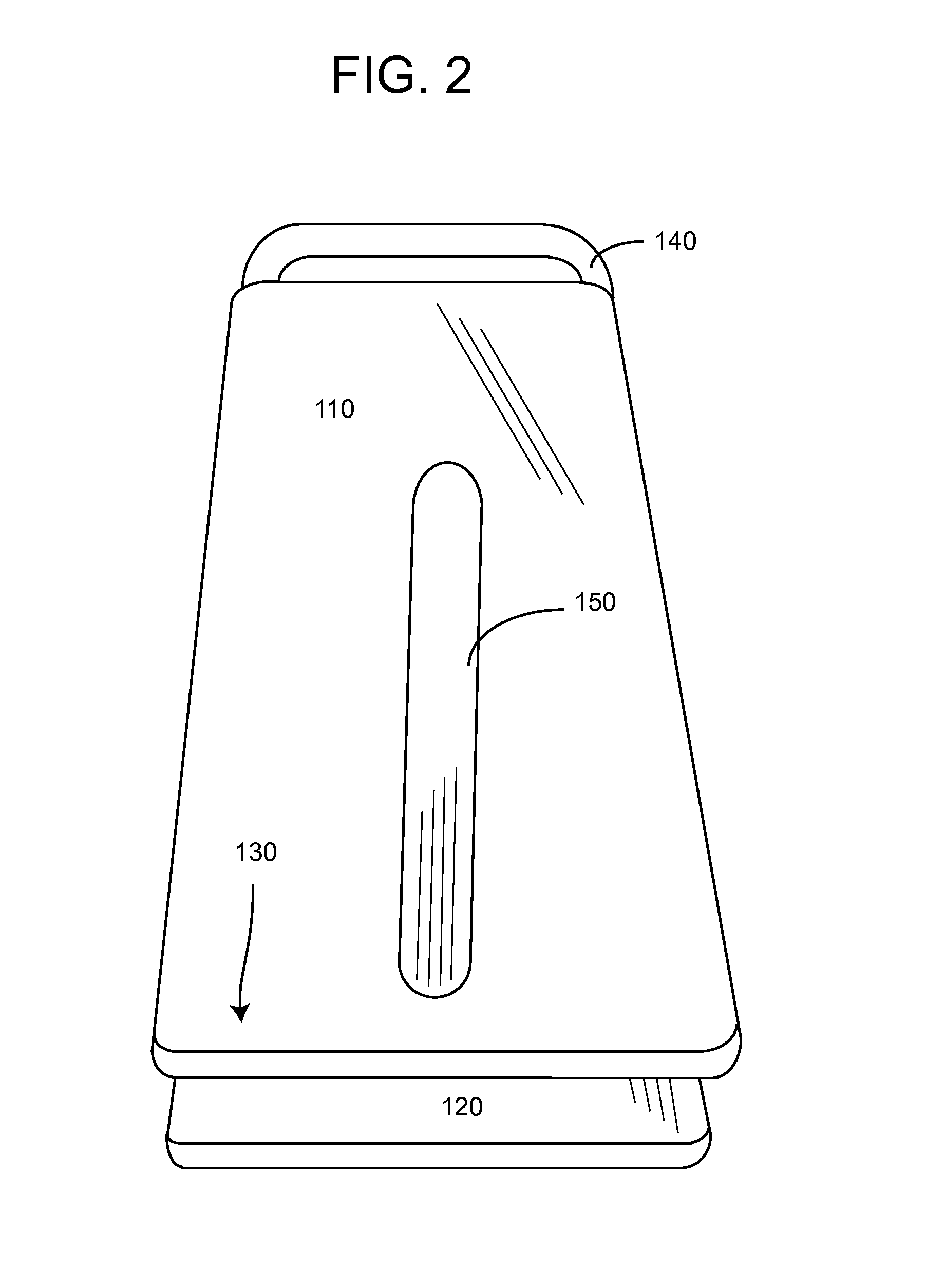
[0021]Now referring to the drawings, wherein like numerals refer to like matter throughout, and more particularly now referring to FIG. 1, there is shown a system of the present invention, generally designated 100, having an outer plate 110 and a spaced apart, but substantially parallel, inner plate 120, where the space therebetween is sized and configured to receive therein, and to slide over, a terminal bottom front end of a bucket of the type used on a front end loader on a tractor, or on a backhoe or other loader or digger machines. A chain receiving ring 150 is shown disposed on an outer surface of outer plate 110, so that a chain or other elongated flexible member, such as a wire, rope, string of links or clips and pins or devises etc., can be used to support an object. Chain receiving ring 150 is shown disposed at an open end 130 of bucket ring attachment 100. Opposite open end 130 is closed end 141, which may be a separate piece of material or a bent section of matter. In on...
PUM
 Abstract
Description
Claims
Application Information