
Differential mechanism restricting device

a technology of restricting device and differential mechanism, which is applied in mechanical equipment, transportation and packaging, and gears, etc., can solve the problems of increasing vehicle weight and increasing the size of differential gears, and achieve the effect of suppressing the large-scale size of the restricting device and avoiding interferen

Active Publication Date: 2015-03-24
HONDA MOTOR CO LTD
View PDF7 Cites 4 Cited by
  • Summary
  • Abstract
  • Description
  • Claims
  • Application Information

AI Technical Summary

Benefits of technology

[0013]In further accordance with the present invention, the differential mechanism restricting device further includes a first rotary shaft and a second rotary shaft. The first rotary shaft is rotated by operation of the first operation element and operates the first slide member. The second rotary shaft is rotated by operation of the second operation element and operates the second slide member. The first rotary shaft and the second rotary shaft are separated from one another in the longitudinal direction of a vehicle with the drive shafts sandwiched therebetween. Therefore, it is possible to easily avoid interference between the members for rotating the first and second rotary shafts, and it is also possible to suppress the large-sizing of the differential mechanism restricting device in the vehicle width direction.
[0014]In further accordance with the present invention, the first rotary shaft and the second rotary shaft are offset from each other in the vehicle width direction. A first arm for rotating the first rotary shaft extends toward a second rotary shaft side in the vehicle width direction. A second arm for rotating the second rotary shaft extends toward a first rotary shaft side in the vehicle width direction. Hence, the first and second arms can be arranged in a compact manner whereby the differential mechanism restricting device can be miniaturized.
[0015]In further accordance with the present invention, the first slide member is formed annularly, a plurality of first pins are formed equidistantly in the circumferential direction, and openings into which a plurality of second pins are insertable are formed between the first pins in the circumferential direction. Since the first slide member is formed annularly, the first slide member has a sufficiently large amount of rigidity even though the plurality of openings are formed in the first slide member. Accordingly, the first slide member enables the differential lock with high rigidity.

Problems solved by technology

As a result, the differential mechanism restricting device that is operated independently by two operation elements becomes large in size leading to an increased size of the differential gear and an increased vehicle weight.

Method used


Image

  • Differential mechanism restricting device
  • Differential mechanism restricting device
  • Differential mechanism restricting device

Examples


Embodiment Construction

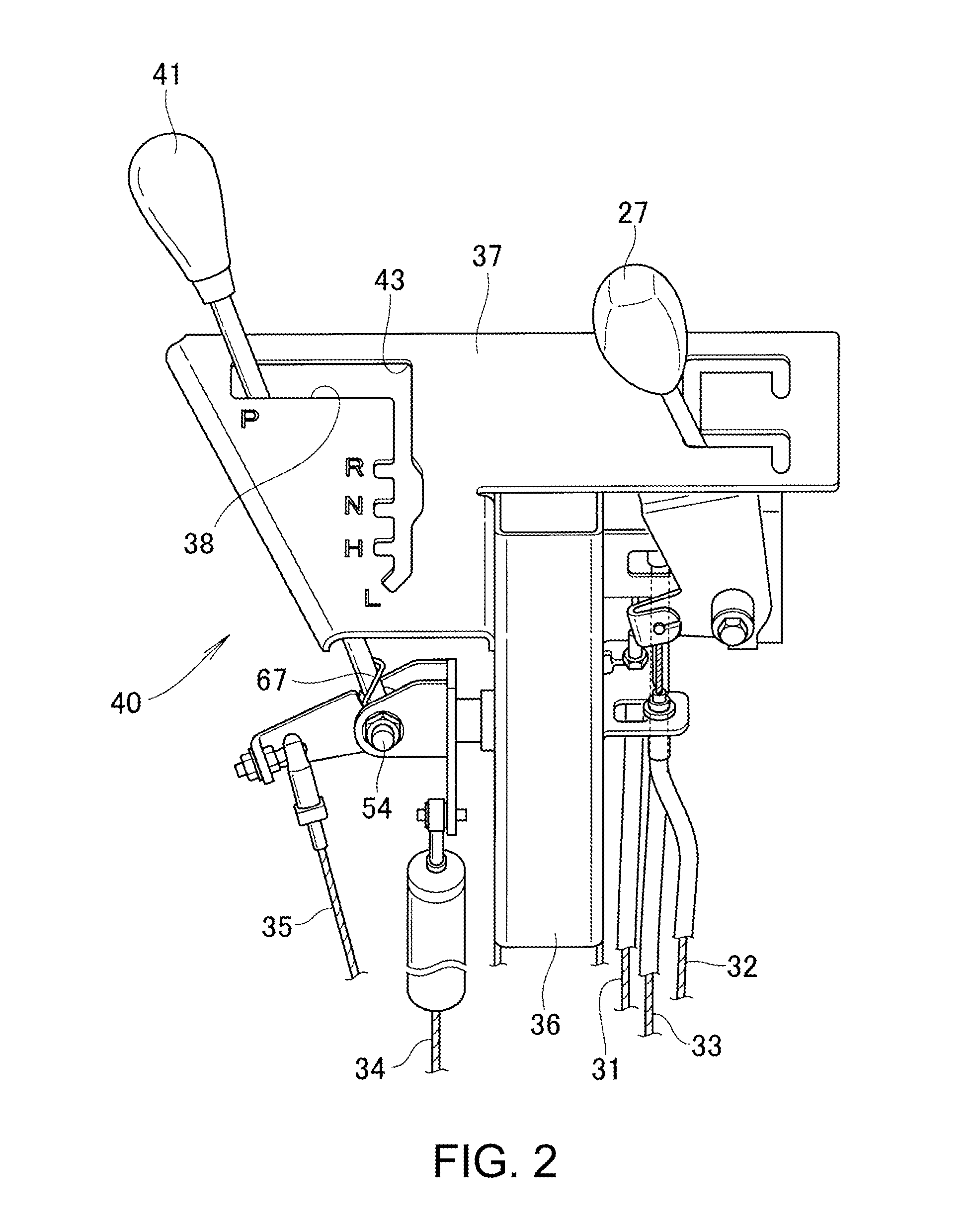
[0032]Hereinafter, an embodiment of the invention is explained in conjunction with attached drawings. First and second operation elements are explained with reference to FIG. 1 to FIG. 7, and the details of a differential mechanism restricting device according to the invention is explained with reference to FIG. 8 and thereafter.

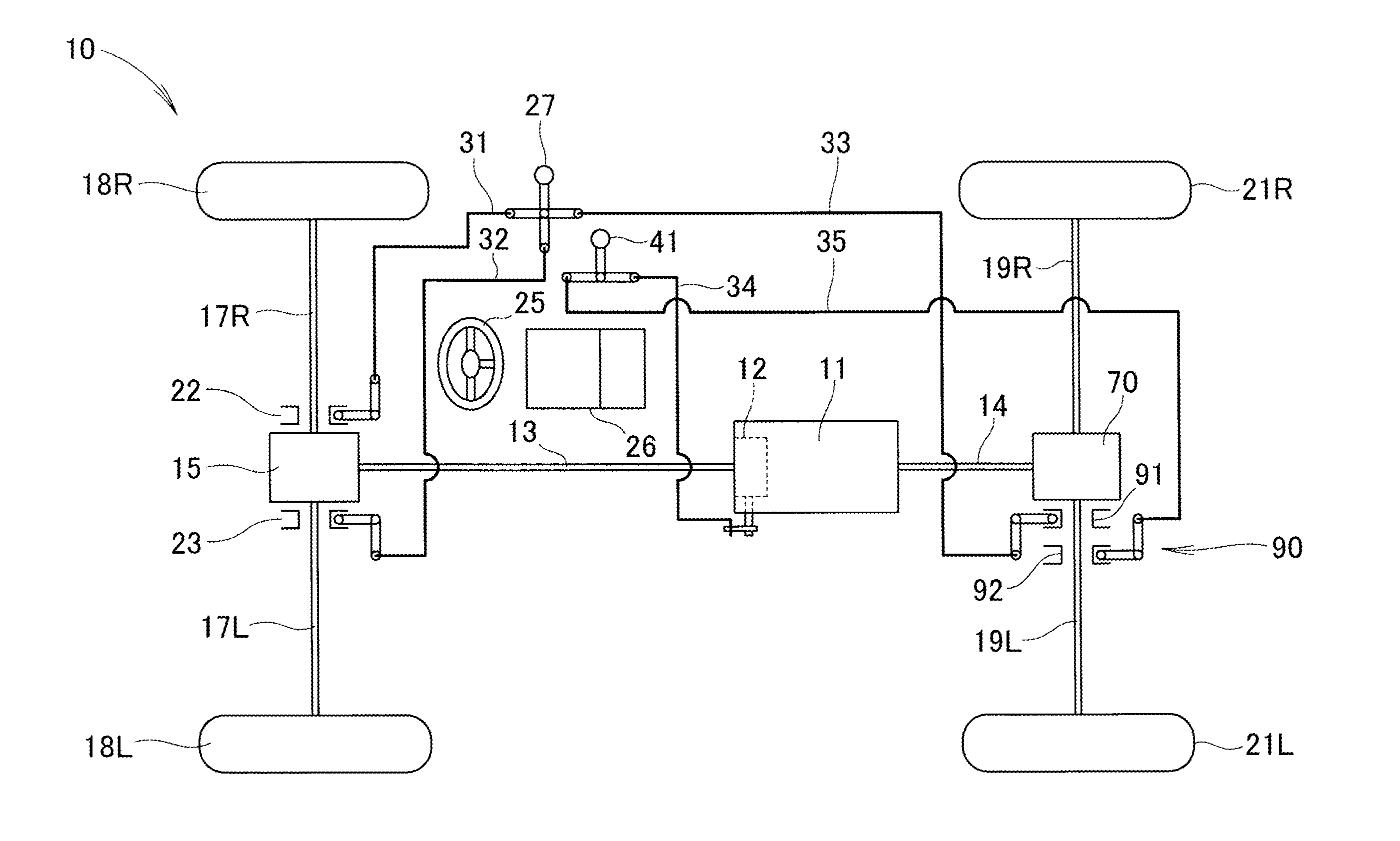
[0033]As shown in FIG. 1, a vehicle 10 includes: a power unit 11, a transmission 12 represented by a gear transmission for changing a change gear ratio at which power is transmitted from the power unit 11; a front propeller shaft 13 and a rear propeller shaft 14 that extend in the longitudinal direction from the transmission 12 for transmitting power; a front differential gear 15 that distributes power transmitted by the front propeller shaft 13 to left and right sides and a rear differential gear 70 that distributes power transmitted by the rear propeller shaft 14 to left and right sides; and front drive wheels 18L, 18R that are driven by the front differen...


PUM


Abstract

A miniaturized differential mechanism restricting device that is mechanically connected to two operation elements. A plurality of holes are formed in an output-side cam, and pin holes are formed in a differential case in a penetrating manner such that the pin holes overlap with the plurality of holes. A plurality of first pins, which pass through the pin holes in a penetrating manner and are fitted in the holes, extend from a first slide member, and a plurality of second pins, which pass through the pin holes in a penetrating manner and are fitted in the holes, extend from a second slide member. The first slide member is moved in the axial direction by a first shift fork, and the second slide member is moved in the axial direction by a second shift fork.

Description

BACKGROUND OF THE INVENTION[0001]1. Field of the Invention[0002]The present invention relates to differential mechanism restricting devices.[0003]2. Description of Related Art[0004]A differential gear is a device that generates a difference in rotational speed between left and right wheels. Depending on a traveling state, it is not necessary to a rotational speed difference between left and right wheels. In such a case, a differential mechanism restricting device is attached to a differential gear. Various proposals have been made with respect to a differential gear provided with a differential mechanism restricting device (see JP-A-2011-117511 (FIG. 3), for example).[0005]As shown in FIG. 3 of JP-A-2011-117511, a fork member (74) (numerals with a parenthesis indicating symbols described in JP-A-2011-117511, the same being applied for the explanation made hereinafter) is swung by a lever member (75) indicated by an imaginary line, and a lock pin (70) is inserted into pin holes (71 a...

Claims


Application Information

Patent Timeline
Patent Type & Authority Patents(United States)
IPC IPC(8): F16H48/06F16H48/20F16H48/24F16H48/30
CPCF16H48/20F16H48/24F16H2048/305
Inventor SATO, KOJIHAYAKAWA, KOSHI
Owner HONDA MOTOR CO LTD
Learn More