Hybrid vehicle

a hybrid vehicle and hybrid technology, applied in hybrid vehicles, machines/engines, engine starters, etc., can solve the problems of increasing power consumption and reducing energy recovery efficiency, and achieve the effects of reducing power consumption, improving energy recovery efficiency during regenerative braking, and avoiding interferen

Inactive Publication Date: 2009-08-04
HONDA MOTOR CO LTD
View PDF16 Cites 12 Cited by
  • Summary
  • Abstract
  • Description
  • Claims
  • Application Information

AI Technical Summary

Benefits of technology

[0011]In accordance with the first aspect, since the driving force of the generator / motor is transmitted to any position of the power transmission pathway between the output shaft of the transmission and the differential gear, it is possible to carry out leg shaft drive in which transmission of the driving force between the generator / motor and the differential gear is carried out without going through the engine and the input shaft, power consumption can be reduced due to a decrease in friction, and the energy recovery efficiency during regenerative braking can be improved. Furthermore, since the generator / motor is disposed at a position sandwiched between the engine and the transmission, the generator / motor can be arranged in the same manner as for the conventional sandwiched generator / motor type, and not only can the leg shaft drive system be employed without greatly modifying the design of the sandwiched generator / motor type transmission, but also the axial dimension does not increase compared with the sandwiched generator / motor type transmission.
[0012]In accordance with the second aspect, since the generator / motor is disposed coaxially with the output shaft, it is possible to easily avoid interference between the generator / motor and the output shaft.
[0013]In accordance with the third aspect, since the starter motor is disposed at a position sandwiched between the engine and the transmission, it is possible to arrange the starter motor without greatly modifying the design of the sandwiched generator / motor type transmission. In particular, since at least parts of the generator / motor and the starter motor overlap each other when viewed in a direction perpendicular to the axis of the input shaft, any increase in the axial dimension of the transmission can be suppressed effectively.
[0014]In accordance with the fourth aspect, since the starter motor is disposed coaxially with the crankshaft, the engine can be started by means of a compact structure, and power can be generated by driving the starter motor by means of the engine.

Problems solved by technology

In the layout of the sandwiched generator / motor type, since the generator / motor is joined to a crankshaft of the engine and an input shaft of the transmission and always rotates integrally therewith, when the generator / motor carries out regenerative braking during deceleration of the vehicle, there are the problems that friction in the engine and the transmission might degrade the energy recovery efficiency, and the friction of the engine is a load on the generator / motor when traveling by means of the generator / motor, thus increasing the power consumption.

Method used


Image

  • Hybrid vehicle
  • Hybrid vehicle
  • Hybrid vehicle

Examples


embodiment 1

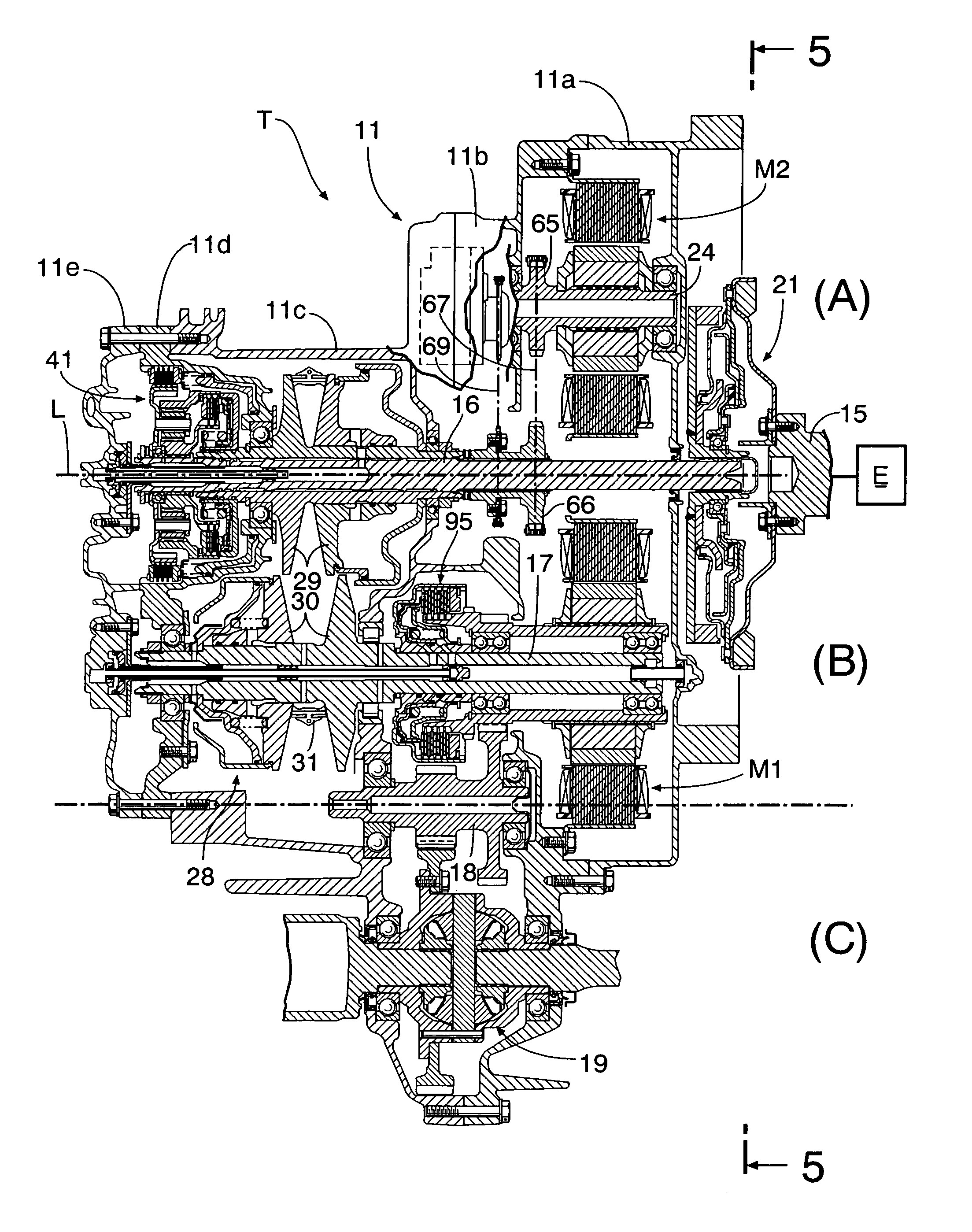
[0036]FIG. 1 to FIG. 6 show a first embodiment of the present invention.

[0037]As shown in FIG. 1, a transmission case 11 of a transmission T mounted in a front part of a vehicle body of a front-engined / front wheel drive vehicle is divided into five, that is, a first casing 11a, a second casing 11b, a third casing 11c, a fourth casing 11d, and a fifth casing 11e. A shaft end of a crankshaft 15 of an engine E faces an opening at the right-hand end of the first casing 11a, and an input shaft 16 (main shaft) of the transmission T, which shares an axis L with the crankshaft 15, is supported in the interior of the transmission case 11. Furthermore, supported within the transmission case 11 are an output shaft 17 (counter shaft) and a reduction shaft 18, which are parallel to the input shaft 16, and disposed beneath the reduction shaft 18 is a differential gear 19.

[0038]As is clear from FIG. 5, the output shaft 17 is disposed above and behind the crankshaft 15 and the input shaft 16, which...

embodiment 2

[0058]FIG. 7 to FIG. 11 show a second embodiment of the present invention. In the second embodiment, components corresponding to the components of the first embodiment are denoted by the same reference numerals and symbols as those of the first embodiment, and duplication of the explanation is thus omitted. It is mainly the parts of the second embodiment that are different from those of the first embodiment that are explained below.

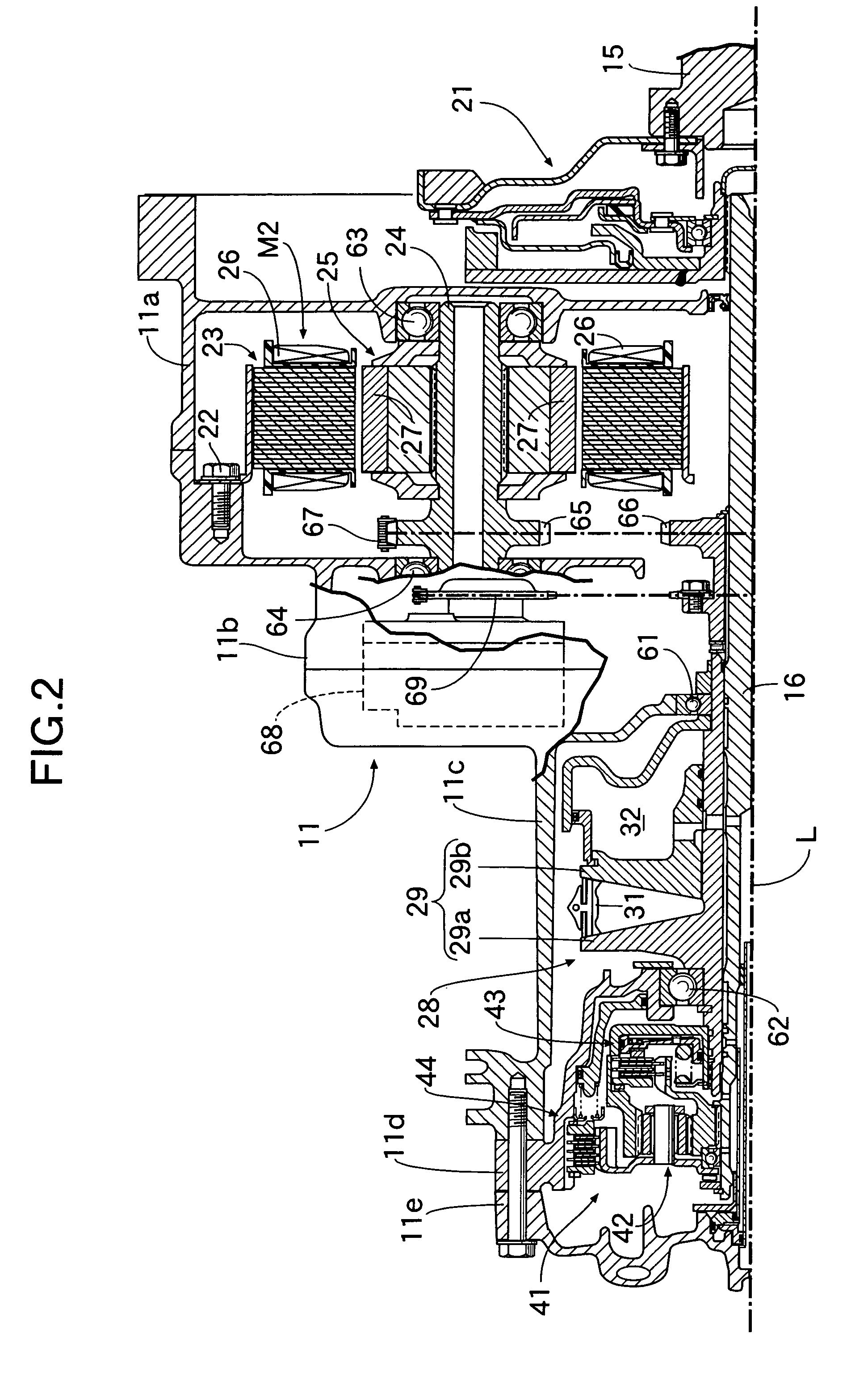
[0059]Firstly, whereas in the first embodiment the starter motor M2 is disposed in a position off the axis L of the input shaft 16, in the second embodiment a starter motor M2 is positioned on an axis L of an input shaft 16. The starter motor M2 is disposed between a crankshaft 15 and a damper 21, a stator 23 thereof is fixed to a first casing 11a via bolts 22, and a rotor 25 thereof is fixed to the crankshaft 15. Therefore, an engine E can be started efficiently by directly cranking the crankshaft 15 by means of the rotor 25 of the starter motor M1, and ...


PUM


Abstract

A hybrid vehicle is provided in which, since the driving force of a generator / motor (M1) is transmitted to the downstream side of an output shaft (17) of a transmission (T) without going through an input shaft (16) thereof and the output shaft (17), it is possible to carry out the so-called leg shaft drive, which prevents the driving force of the generator / motor (M1) from dragging along an engine (E), the input shaft (16), and the output shaft (17), thus reducing power consumption and enhancing energy recovery efficiency during regenerative braking. Furthermore, since the generator / motor (M1) is disposed at a position sandwiched between the engine (E) and the transmission (T), it is possible to employ the same layout for the generator / motor (M1) as for a conventional sandwiched generator / motor type, and the leg shaft drive system can be employed without greatly modifying the design of the transmission (T).

Description

TECHNICAL FIELD[0001]The present invention relates to a hybrid vehicle that can travel by means of either one or both of the driving force of an engine and the driving force of a generator / motor.BACKGROUND ART[0002]In such a hybrid vehicle, the layout for an engine, a generator / motor, and a transmission that is conventionally employed is in general of a so-called sandwiched generator / motor type in which a thin generator / motor is sandwiched between the engine and the transmission. In the layout of the sandwiched generator / motor type, since the generator / motor is joined to a crankshaft of the engine and an input shaft of the transmission and always rotates integrally therewith, when the generator / motor carries out regenerative braking during deceleration of the vehicle, there are the problems that friction in the engine and the transmission might degrade the energy recovery efficiency, and the friction of the engine is a load on the generator / motor when traveling by means of the gener...

Claims


Application Information

Patent Timeline
Patent Type & Authority Patents(United States)
IPC IPC(8): B60K6/24B60K6/26B60K6/36B60K6/44B60K6/48B60K6/54B60K6/543B60K17/04B60L50/16F02D29/00F02D29/02F02N11/00F02N11/04
CPCB60K6/40B60K6/442B60K6/543Y02T10/92Y02T10/6234Y02T10/62
Inventor ABE, NORIYUKIOKADA, YOSHIO
Owner HONDA MOTOR CO LTD
Why Eureka
Try Eureka