Separating device and method with a return flow of heavy fraction

Active Publication Date: 2015-03-31
SULZER MANAGEMENT AG
View PDF3 Cites 7 Cited by
  • Summary
  • Abstract
  • Description
  • Claims
  • Application Information

AI Technical Summary

Benefits of technology

[0005]The object of the invention is to provide a device for separating a heavy fraction from a fluid which, while reta

Problems solved by technology

It is additionally noted that the separation of the fractions is understood to mean at least partial separation of two fractions such that a signif

Method used


Image

  • Separating device and method with a return flow of heavy fraction
  • Separating device and method with a return flow of heavy fraction
  • Separating device and method with a return flow of heavy fraction

Examples


Embodiment Construction

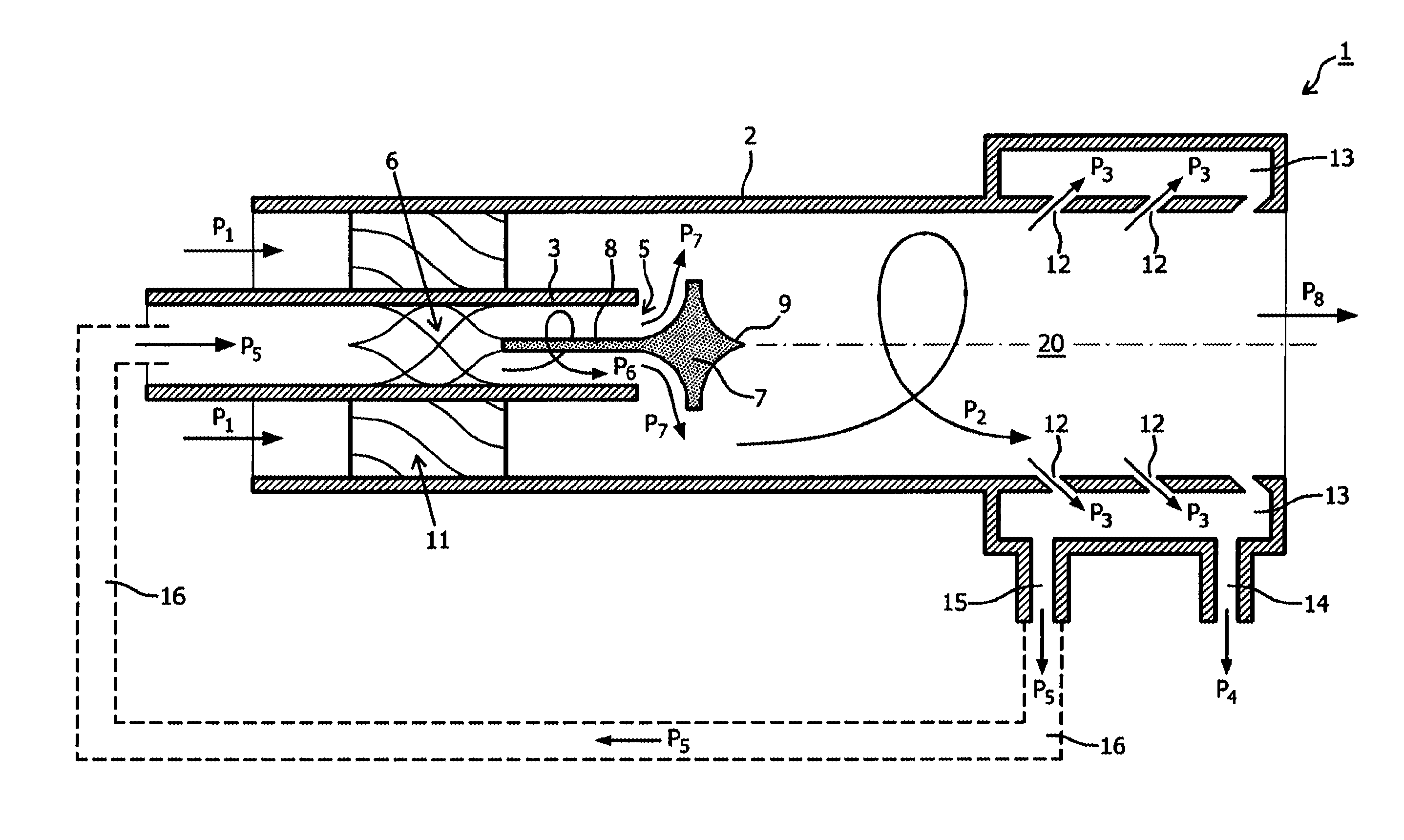
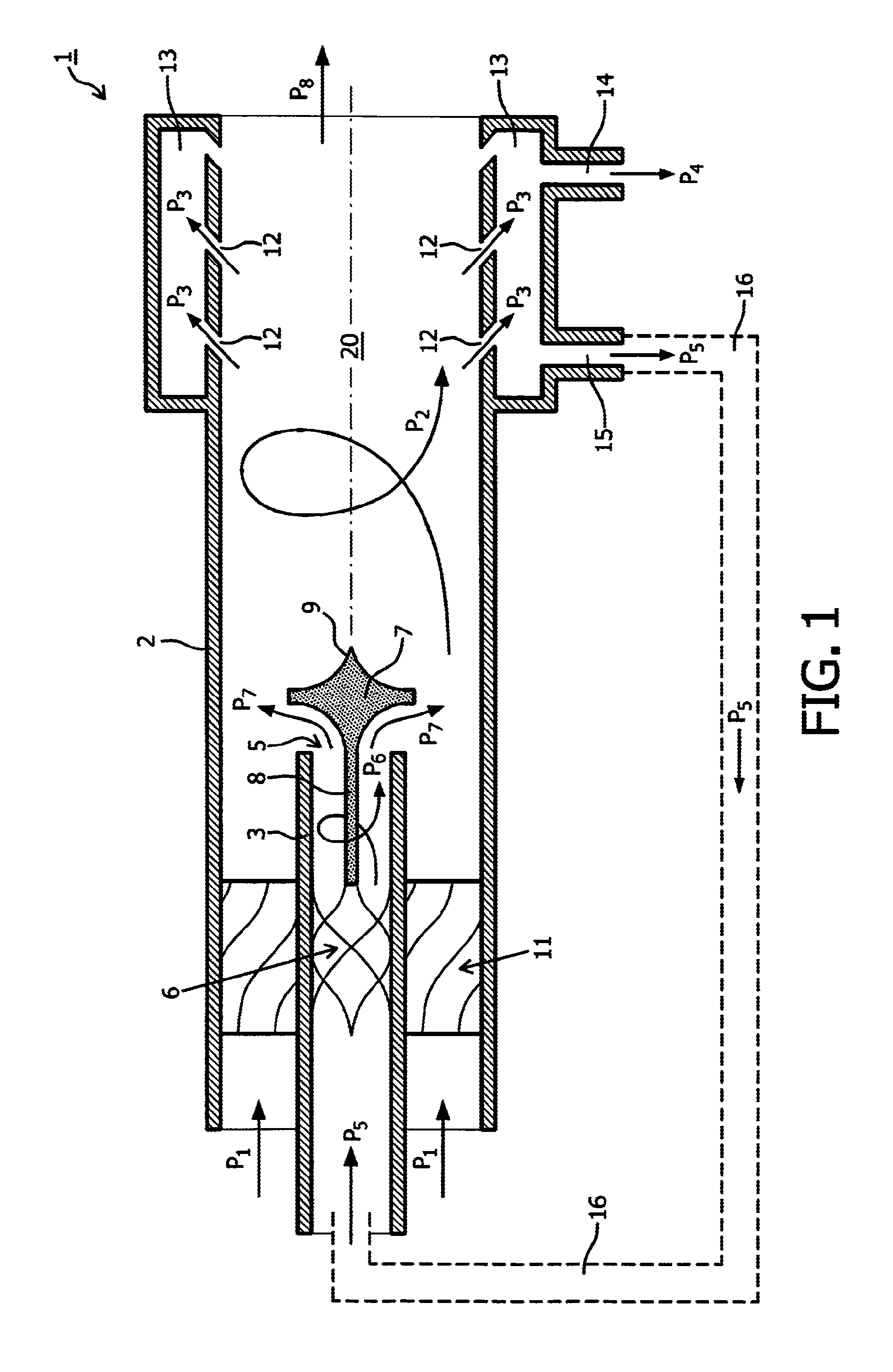
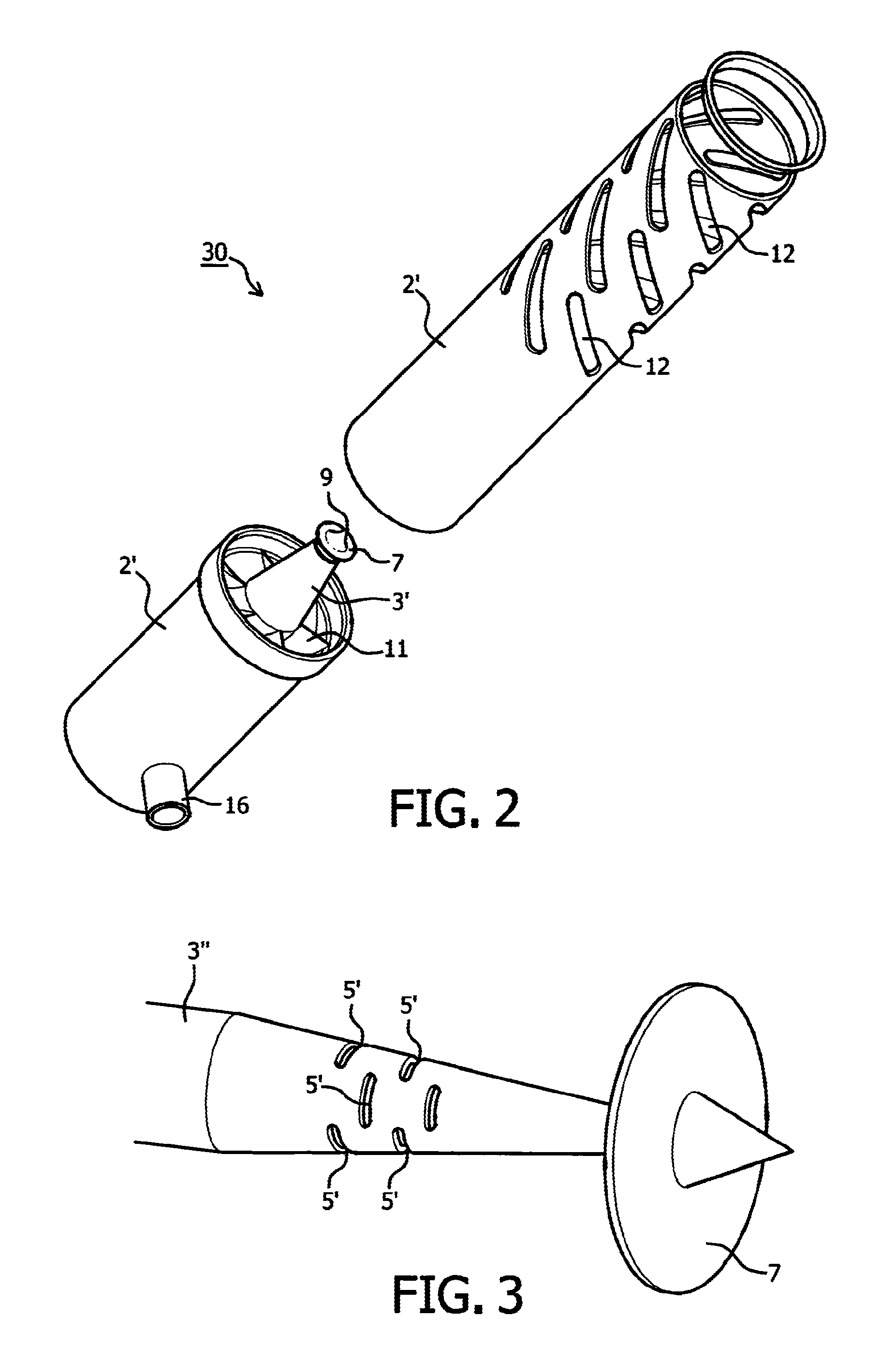
[0025]FIG. 1 shows a separating device 1 with a main channel 20 surrounded by a cylindrical housing 2. Concentric to the main channel 20 an additional supply conduit 3 extends into the cylindrical housing 2. The additional supply conduit 3 is provided with an outlet 5 that encircles (surrounds) the circumference of the additional supply conduit 3. In the additional supply conduit 3 swirl means 6 are located, e.g. made out of helical blades. Downstream the outlet 5 of the additional supply conduit 3 and coaxial with the additional supply conduit 3 (and thus also coaxial with the main channel 20) a substantially dish-shaped deflection body 7 is located. The deflection body 7 is connected with a coaxial pen 8 to the swirl means 6, which pen 8 has an increasing diameter with decreasing distance to the deflection body 7. The deflection body 7 is at its side away from the additional supply conduit 3 provided with a projecting part 9 that is, among others, provided to prevent turbulent flo...


PUM

PropertyMeasurementUnit
Fractionaaaaaaaaaa
Flow rateaaaaaaaaaa
Diameteraaaaaaaaaa

Abstract

The invention relates to a device for separating a heavy fraction from a fluid, comprising: a main channel; swirl means in the main channel; collecting means adjoining the main channel for collecting the discharge heavy fraction; a concentric additional supply conduit with an outlet and extending into the cylindrical housing; a return channel connecting the collecting means with the additional supply conduit, and deflection means wherein the outlet is encircling the circumference of the additional supply conduit. The invention also relates to a method for separating a heavy fraction from a fluid using such a device.

Description

BACKGROUND OF THE INVENTION[0001]1. Field of the Invention[0002]The invention relates to a device for separating a heavy fraction from a fluid, comprising: a main channel, surrounded by a substantially cylindrical housing; swirl means, positioned in the main channel, for transferring a rotating movement component to the fluid moving through the main channel; collecting means, which in radially direction to openings in the cylindrical housing adjoin to the main channel, for collecting the discharged heavy fraction; a concentric additional supply conduit, provided with an outlet, which additional supply conduit at least partly extends into the cylindrical housing; a return channel, which connects the collecting means with the additional supply conduit; and the additional supply conduit is provided with deflection means, which are positioned downstream of the outlet, for providing a movement component in radial direction to the returning fluid fraction moving through the return channel...

Claims


Application Information

Patent Timeline
IPC IPC(8): B04C3/00B04C3/06B01D45/16
CPCB04C3/06B01D45/16B04C3/00Y10T137/87249Y10T137/0318
Inventor SCHOOK, ROBERT
Owner SULZER MANAGEMENT AG
Why Eureka
Try Eureka