Method, tool, and device for assembling a plurality of partial floor plans into a combined floor plan

a technology of partial floor plans and combined floor plans, applied in the field of floor plans, can solve the problems of partial floor plans not fitting seamlessly together, affecting the quality of floor plans, and varying in complexity and precision of tools,

Active Publication Date: 2015-03-31
SENSOPIA
View PDF5 Cites 35 Cited by
  • Summary
  • Abstract
  • Description
  • Claims
  • Application Information

AI Technical Summary

Problems solved by technology

These tools vary in complexity and precision.
No matter how precise the measurements, many factors may prevent partial floor plans from fitting seamlessly together.
For instance, one may read different measures when measuring a wall from one side and the other; room corner angles are seldom square in reality even though they were meant to be; wall thickness is not uniform, often hiding plumbing, wires, ventilation ducts, or structural elements not apparent to the eye; floors and ceilings are not always parallel, as is the case for opposing walls; construction materials compress and stretch over time, distorting building structure.
It does not attempt to correct measurement errors, nor does it attempt to make various portions of a floor plan fit together.

Method used


Image

  • Method, tool, and device for assembling a plurality of partial floor plans into a combined floor plan
  • Method, tool, and device for assembling a plurality of partial floor plans into a combined floor plan
  • Method, tool, and device for assembling a plurality of partial floor plans into a combined floor plan

Examples


Embodiment Construction

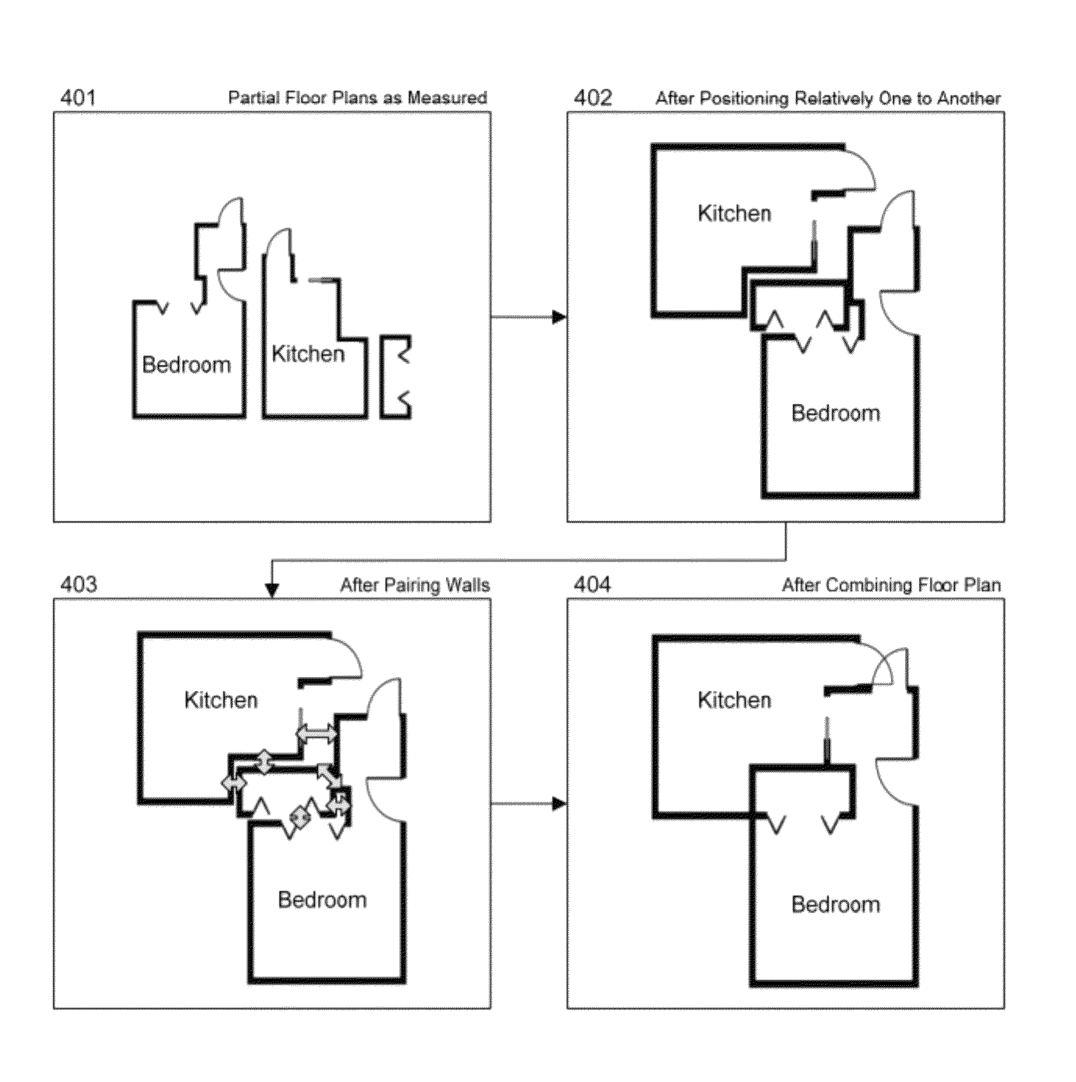
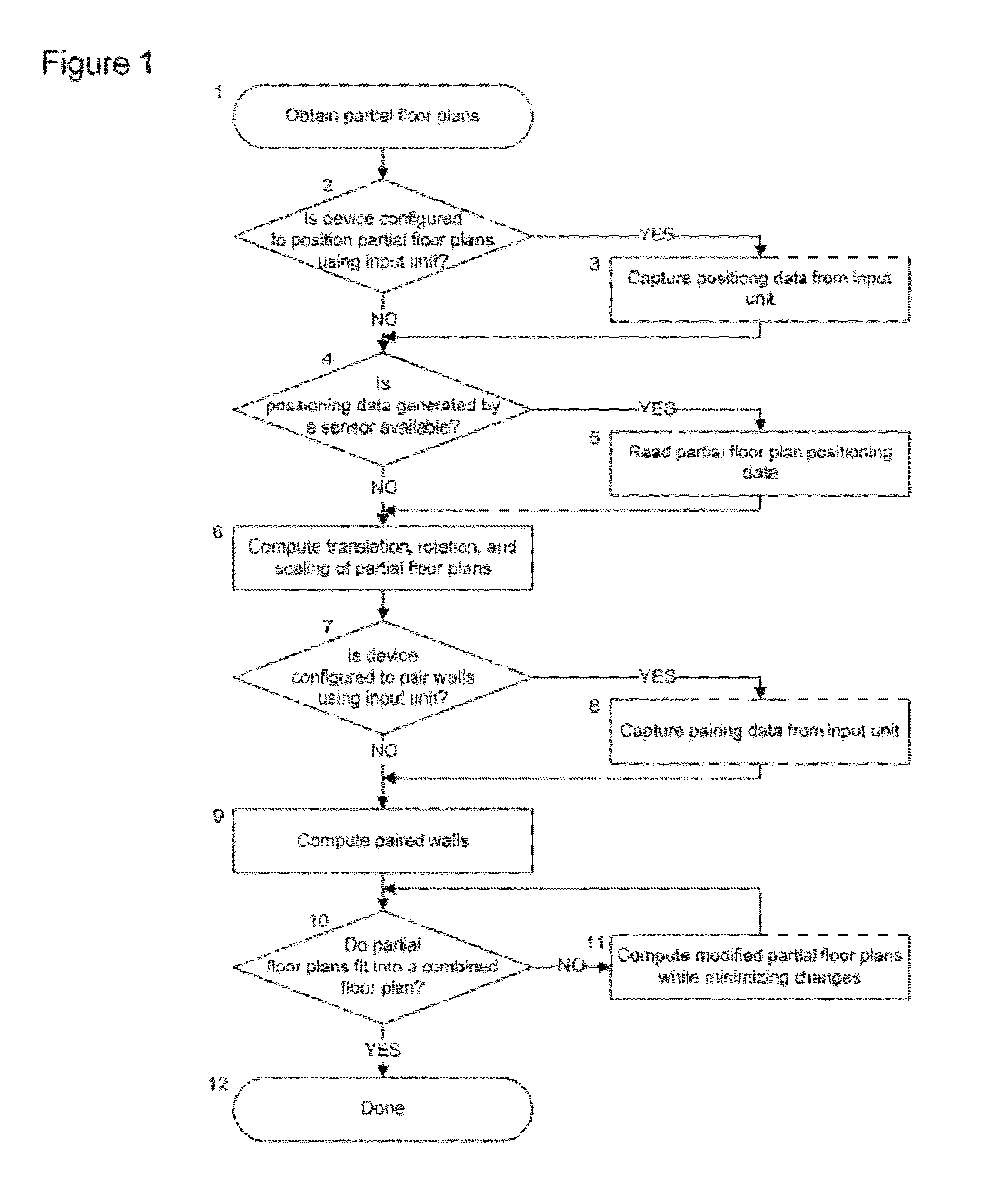
[0018]Reference is now made to FIG. 1, wherein there is shown an example of a simplified flow diagram describing the various steps of the method.

[0019]According to one of the preferred embodiments of the invention, capturing positioning data from an input unit 3 and reading partial floor plan positioning data 5 can be performed in any order, even simultaneously.

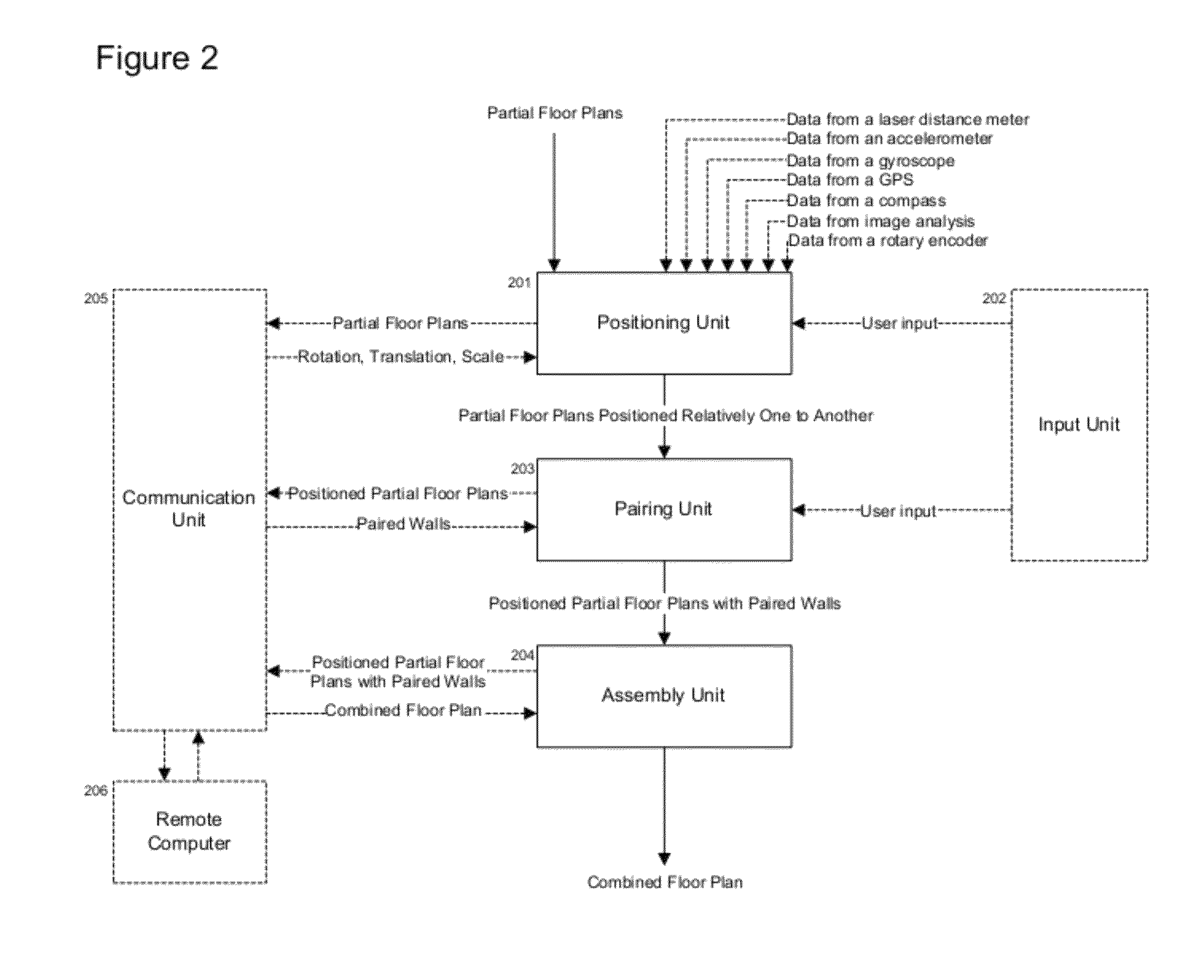
[0020]According to another preferred embodiment of the invention, the positioning data captured from an input unit 3 comprises a translation, a rotation, and a scaling for each partial floor plan. The translation and the rotation may be absent or equal to zero if there is no need to translate or rotate the partial floor plan. Similarly, the scaling may be absent or equal to one if there is no need to scale the partial floor plan.

[0021]According to another preferred embodiment of the invention, the positioning unit makes a first attempt at computing a translation, a rotation, and a scaling 6 in order to determine if capturing ...


PUM


Abstract

A method, tool, and device for assembling a plurality of partial floor plans into a combined floor plan by means of an electronic device. The method involves positioning partial floor plans relatively one to another, pairing substantially aligned walls, and computing modified partial floor plans that can be assembled into a combined floor plan.

Description

BACKGROUND OF THE INVENTION[0001]1. Field of the Invention[0002]The present invention relates to floor plans.[0003]2. Description of the Prior Art[0004]Floor plans of existing buildings are made using distance measurement tools. These tools vary in complexity and precision. An example of a distance measurement tool is the tape measure, which requires manually extending a ruler between two points and reading the distance that aligns with the second point. Another example of a distance measurement tool is the laser distance meter, which sends a laser pulse in a narrow beam towards the object and measure the time taken by the pulse to be reflected off the target and returned to the device.[0005]During the measuring phase, measurements are typically grouped by floor, by room, or by some other criteria that simplifies assigning them to floors, walls, doors, and windows on a floor plan. This grouping often yields partial floor plans, which then have to be assembled into a complete floor p...

Claims


Application Information

Patent Timeline
Patent Type & Authority Patents(United States)
IPC IPC(8): G06F17/50G01C15/00G01S17/08
CPCG01C15/00G06F17/5004G01S17/08G06F17/50G06F2217/02G06F2217/04G06F30/13G06F2111/02G06F2111/20G06F30/00
Inventor MALKA, FRANCIS RUBENDESFORGES, GILLES JEAN
Owner SENSOPIA
Why Eureka
Try Eureka