Brake system for a vehicle and method for operating a brake system of a vehicle

a brake system and vehicle technology, applied in the direction of brake systems, vehicle components, brake components, etc., can solve the problems of relatively high price of brake-by-wire brake systems, the inability of the regenerative brake system to exert a regenerative braking torque on the wheels of the vehicle, etc., to achieve stable braking performance, improve the distribution of brake force, and improve the effect of handling performan

Inactive Publication Date: 2015-04-07
ROBERT BOSCH GMBH
View PDF39 Cites 1 Cited by
  • Summary
  • Abstract
  • Description
  • Claims
  • Application Information

AI Technical Summary

Benefits of technology

[0009]In the brake system according to the present invention, the driver has the option of braking actively into the first wheel brake cylinder and / or into the second wheel brake cylinder by actuating a brake input element coupled to the master brake cylinder. Additionally, a brake pressure in the first wheel brake cylinder and / or in the second wheel brake cylinder may be actively built up / increased via an actuation of the pump decoupled from / independently of the actuation of the brake input element by the driver. In spite of the common use of the pump for setting a desired brake pressure in the first wheel brake cylinder and / or in the second wheel brake cylinder, an undesired brake medium transfer between the first brake circuit and the second brake circuit is preventable via the first non-return valve and the second non-return valve. In the invention described here, this advantage is realizable in particular at comparatively low costs of the two non-return valves. Thus, it is possible to generate in a cost-effective manner a brake pressure in the first and / or second wheel brake cylinder that is not attributable to an exertion of force on the master brake cylinder.
[0026]Furthermore, the brake system may have exactly eight controllable valves, which are controllable at least into an open state and into a closed state via an electrical signal provided by a control device of the brake system. The limitation of the valves required by the brake system, which are electrically switchable at least into the open state and into the closed state, to the number of eight reduces the requirements and / or the costs for an electronics suited as a control device.

Problems solved by technology

However, operating the electric motor, for example the electric drive motor, in generator mode typically requires a certain minimum speed of the vehicle.
A recuperative brake system is thus frequently unable to exert a regenerative braking torque on the wheels of the vehicle for as long as it takes for the moving vehicle to come a standstill.
Due to their complex electronics, mechanics and hydraulics, however, brake-by-wire brake systems are relatively expensive.

Method used


Image

  • Brake system for a vehicle and method for operating a brake system of a vehicle
  • Brake system for a vehicle and method for operating a brake system of a vehicle
  • Brake system for a vehicle and method for operating a brake system of a vehicle

Examples


Embodiment Construction

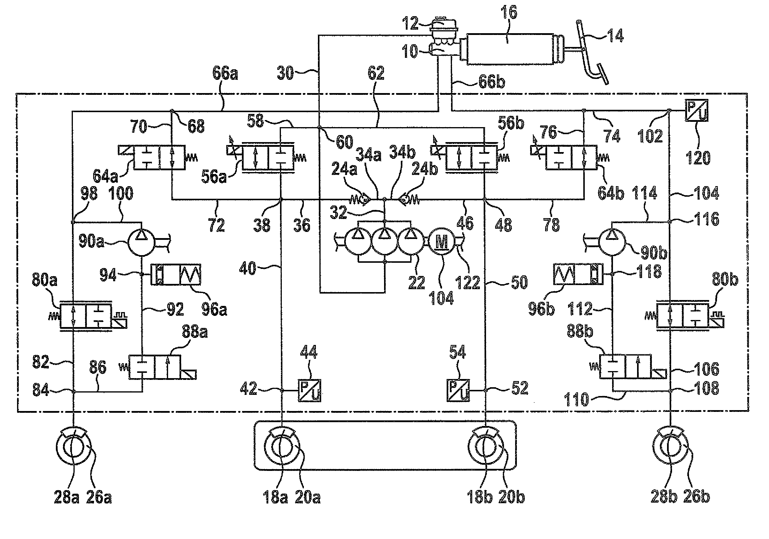
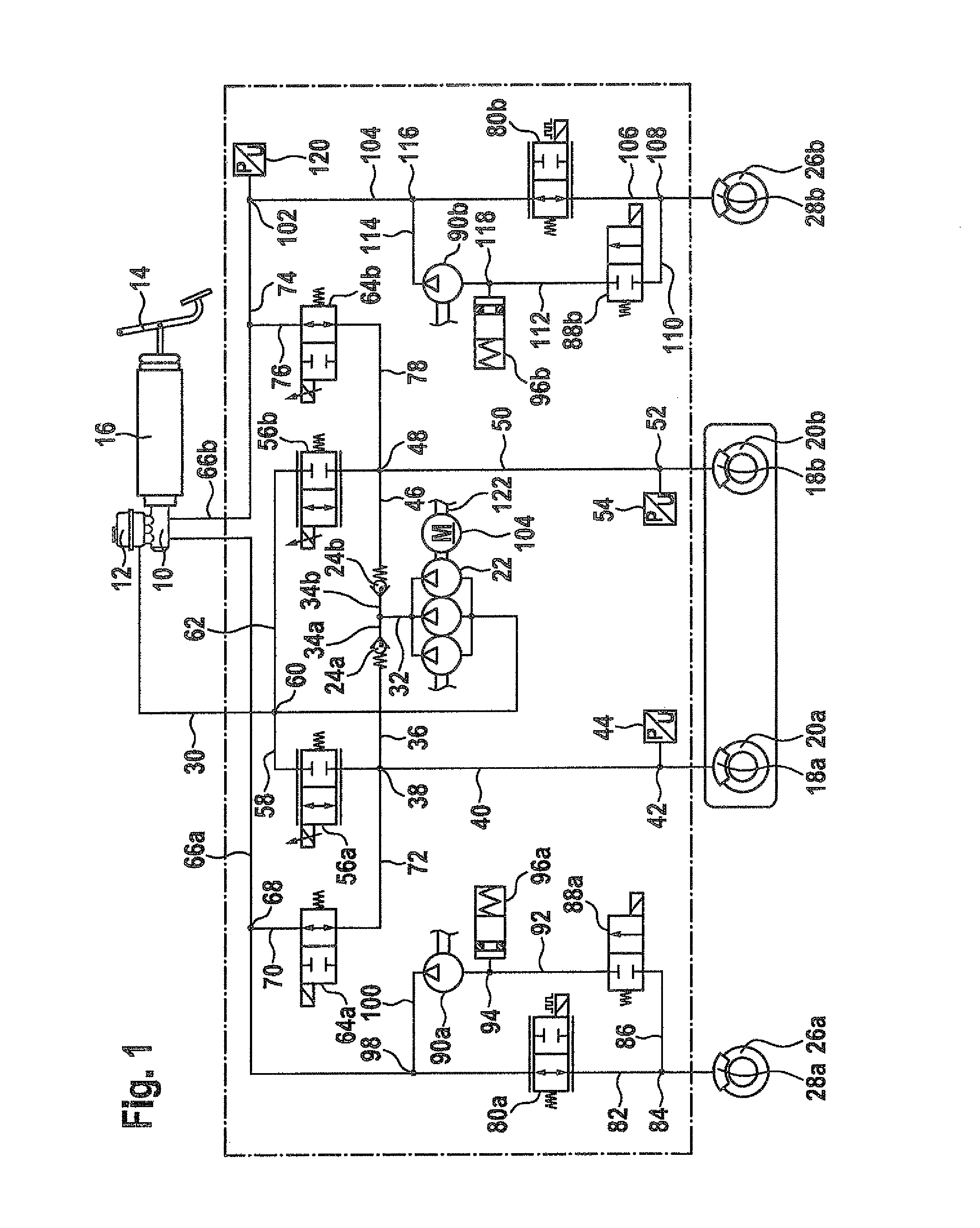
[0034]FIG. 1 shows a circuit diagram of a first specific embodiment of the brake system. The brake system shown schematically in FIG. 1 is usable not only in an electric or hybrid vehicle. Instead, the brake system may also be used in a vehicle, for example, to ensure a preferred brake force distribution on the wheels of the vehicle when braking during cornering and / or driving in reverse. The indications, described below, of the use of the brake system in an electric or hybrid vehicle are to be understood merely by way of example.

[0035]The brake system comprises a master brake cylinder 10 and an additional brake medium reservoir 12. A brake medium exchange bore such as a snifting bore, for example, may be developed between master brake cylinder 10 and brake medium reservoir 12. Master brake cylinder 10 and brake medium reservoir 12, however, may also be developed without a hydraulic connection.

[0036]A brake input element 14 such as a brake pedal may be coupled to master brake cylind...


PUM


Abstract

A brake system and method for operating same for a vehicle having a master brake cylinder, a brake medium reservoir, a first wheel brake cylinder, into which a first brake medium volume is displaceable from the master cylinder, a second wheel brake cylinder, into which a second brake medium volume is displaceable from the master cylinder, and a pump, which is hydraulically connected to the brake medium reservoir, the first wheel brake cylinder being hydraulically connected to the pump via a first non-return valve and the second wheel brake cylinder being hydraulically connected to the pump via a second non-return valve so that the pump can pump a third brake medium volume from the brake medium reservoir through the first non-return valve into the first wheel brake cylinder and a fourth brake medium volume from the brake medium reservoir through the second non-return valve into the second wheel brake cylinder.

Description

FIELD OF THE INVENTION[0001]The present invention relates to a brake system for a vehicle. Furthermore, the present invention relates to a method for operating a brake system of a vehicle.BACKGROUND INFORMATION[0002]Electric and hybrid vehicles have a brake system designed for recuperative braking including an electric motor operated as a generator during recuperative braking. Following an intermediate storage, the electrical energy recovered during recuperative braking may be used for accelerating the vehicle.[0003]This makes it possible to reduce power loss, which a conventional vehicle incurs when braking frequently in travel, energy consumption and pollutant emission of the electric or hybrid vehicle.[0004]However, operating the electric motor, for example the electric drive motor, in generator mode typically requires a certain minimum speed of the vehicle. A recuperative brake system is thus frequently unable to exert a regenerative braking torque on the wheels of the vehicle f...

Claims


Application Information

Patent Timeline
Patent Type & Authority Patents(United States)
IPC IPC(8): B60T8/34B60T8/36B60T8/42B60T8/48
CPCB60T8/4827B60T8/348B60T8/3655B60T8/4275B60T8/36B60T8/48
Inventor KUNZ, MICHAELSTRENGERT, STEFAN
Owner ROBERT BOSCH GMBH
Why Eureka
Try Eureka