
Display device, terminal device, display system, display method, and image alteration method

a technology of display device and terminal device, which is applied in the field of display device, terminal device, display system, display method, and image alteration method, and can solve problems such as time-consuming operation

Active Publication Date: 2015-04-07
SEIKO EPSON CORP
View PDF15 Cites 1 Cited by
  • Summary
  • Abstract
  • Description
  • Claims
  • Application Information

AI Technical Summary

Benefits of technology

The present invention relates to a technology that allows a display device to generate an image quickly using image information that is transmitted from a host device. The invention also prevents image configuration alteration requests from occurring simultaneously, which can reduce flickering or other image quality issues. The technical effects of this invention include improved image quality and reduced flickering on the display device.

Problems solved by technology

However, in conferences, for example, in the case in which the presenter enlarges the image of a participant using a remote controller in response to the request from the participant, the presenter needs to identify the image of the participant, understand the contents of the request, and operate the remote controller in accordance with the request, and therefore, the operation takes time.

Method used


Image

  • Display device, terminal device, display system, display method, and image alteration method
  • Display device, terminal device, display system, display method, and image alteration method
  • Display device, terminal device, display system, display method, and image alteration method

Examples


first embodiment

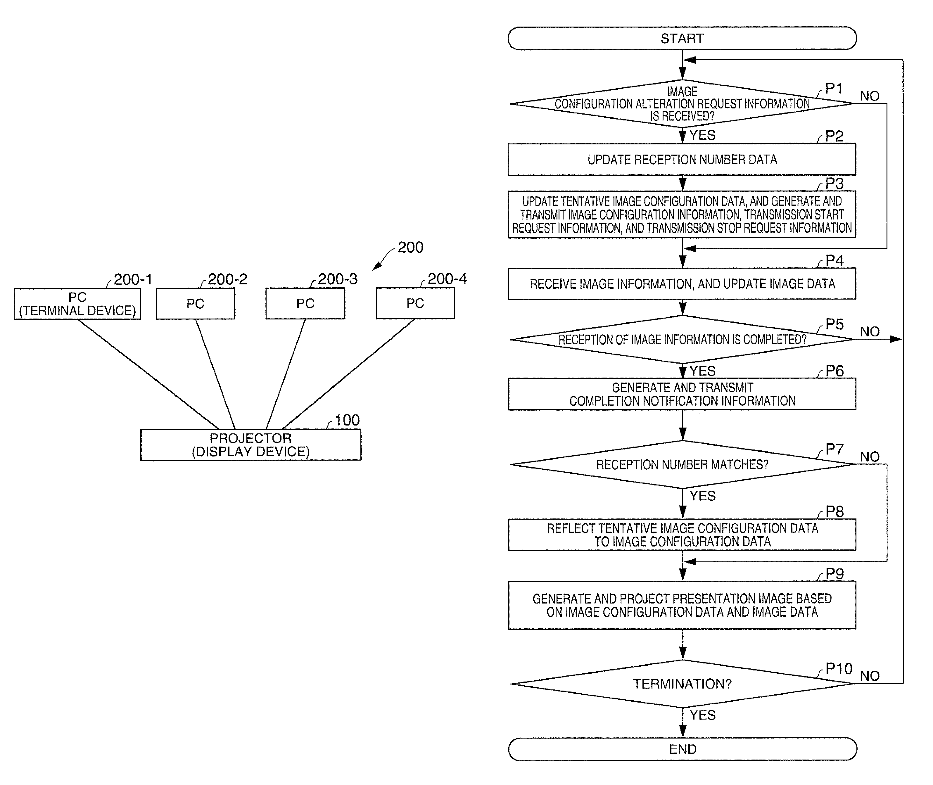
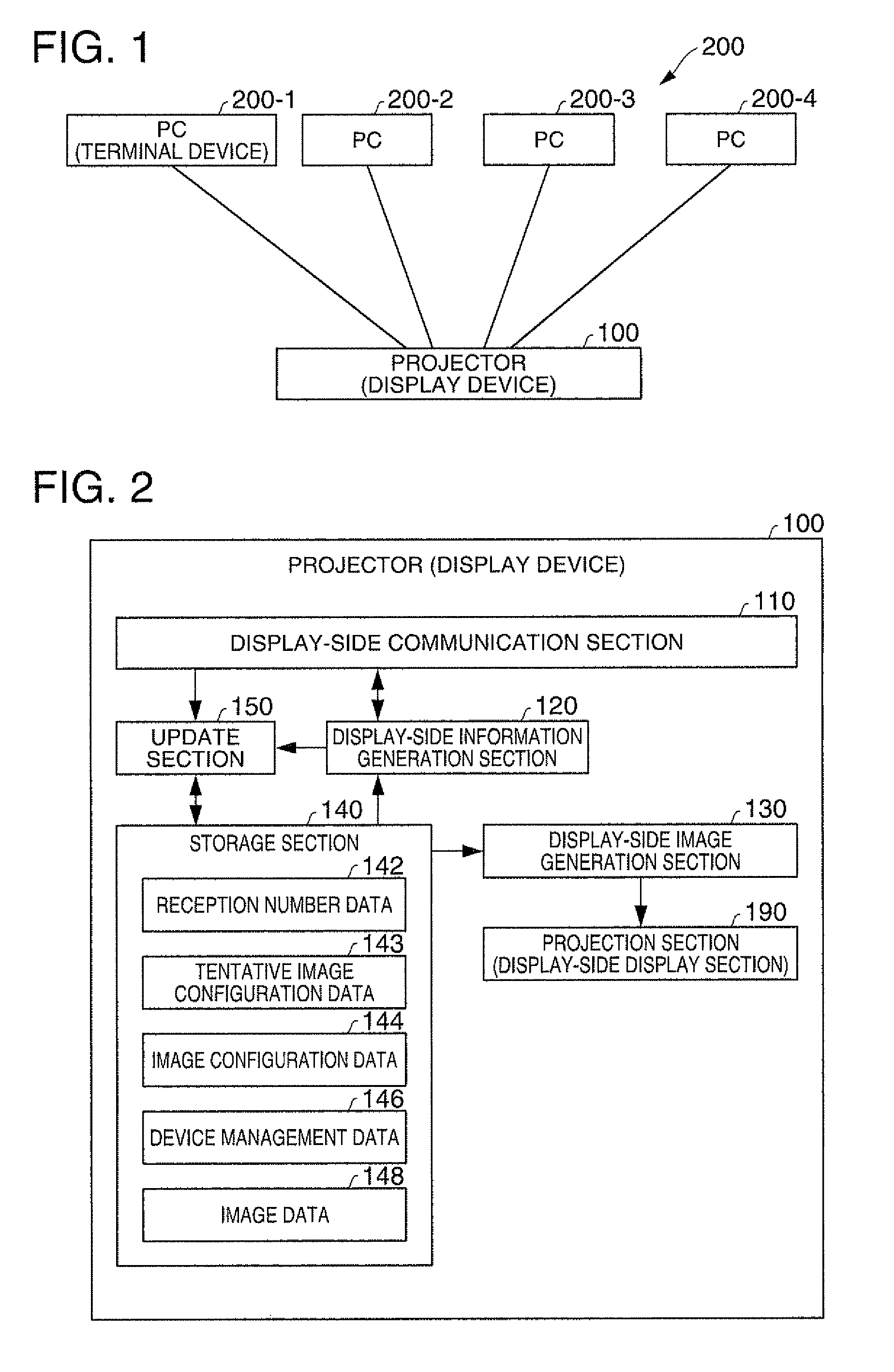
[0036]FIG. 1 is a diagram showing an example of a display system according to a first embodiment of the invention. The display system is configured including a projector 100 as a type of display device, and four PCs 200-1 through 200-4 as a type of terminal devices. Each of the PCs 200 is configured to be able to perform communication with the projector 100 in a wireless manner (or wired manner as well). Here, it is assumed that four users view the presentation image projected by the projector 100 while performing operations using the respective PCs 200.

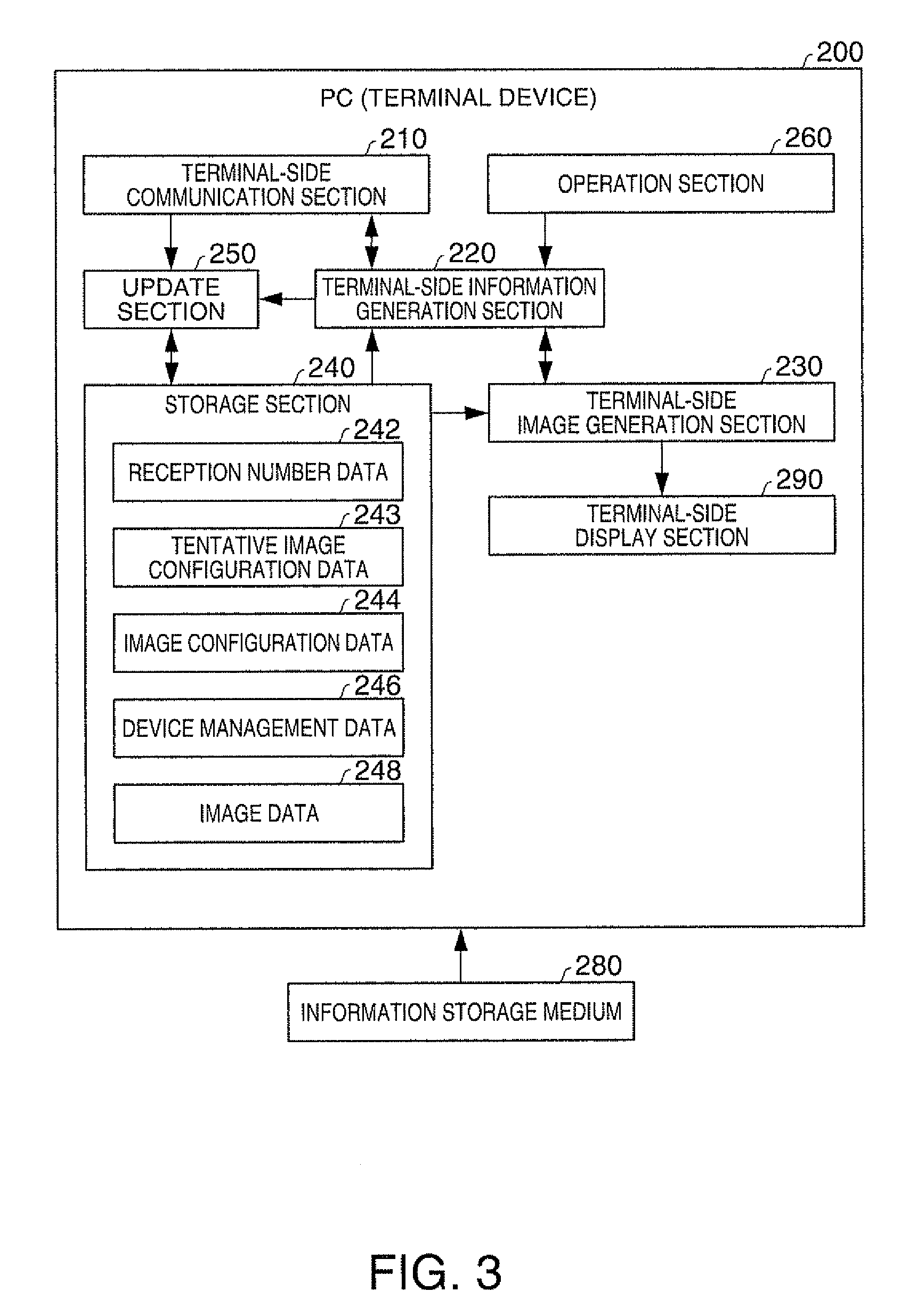
[0037]The projector 100 has functions of receiving image configuration alteration request information from the PCs 200, altering individual images (second images) constituting the presentation image (a first image) in accordance with the image configuration alteration request information, and projecting the presentation image thus altered. Further, the PCs 200 each have a function of determining whether or not the image configuration...

second embodiment

[0089]Although in the first embodiment there is used a single display device, it is also possible to use a plurality of display devices. FIG. 13 is a diagram showing an example of a display system according to a second embodiment of the invention.

[0090]The display system according to the present embodiment is configured including a projector 100-1 for independently performing the configuration of the image, a projector 100-2 for dependently performing the configuration of the image, and the four PCs 200-1 through 200-4.

[0091]It should be noted that the projector 100-1 and the projector 100-2 do not communicate with each other.

[0092]Specifically, the projector 100-1 functions as the projector 100 of the first embodiment, and the projector 100-2 updates the reception number data 142, the image configuration data 144, and so on based on the image configuration information from each of the PCs 200, and projects the presentation image based on the image configuration data 144.

[0093]As de...


PUM


Abstract

A display device includes: a display-side communication section adapted to receive image configuration alteration request information related to a configuration of a first image and image information of at least one second image constituting the first image from at least one terminal device; a display-side image generation section adapted to generate the first image based on the image configuration alteration request information and the image information; and a display-side display section adapted to display the first image.

Description

[0001]The entire disclosure of Japanese Patent Application No. 2010-057357, filed Mar. 15, 2010 is expressly incorporated by reference herein.BACKGROUND[0002]1. Technical Field[0003]The present relates to a display device, a terminal device, a display system, a display method, and an image alteration method.[0004]2. Related Art[0005]For example, in JP-A-2004-54783, there is described a display system for receiving the captured image data, on which the size conversion process is performed, from a plurality of terminal devices, and combining the image data into image data of one frame and then displaying the frame. Further, in this document, there is also described the fact that the image in a specific terminal device is displayed in an enlarged manner, deleted, or added by operating a remote controller of the display device to thereby set the priority.[0006]However, in conferences, for example, in the case in which the presenter enlarges the image of a participant using a remote cont...

Claims


Application Information

Patent Timeline
Patent Type & Authority Patents(United States)
IPC IPC(8): G06F15/16G06F3/14H04N9/31
CPCG06F3/1454H04N9/3179
Inventor ARIZUMI, TAKEAKIYOSHIDA, MITSUHIROYOKOYAMA, ISSEI
Owner SEIKO EPSON CORP
Learn More