Membrane valve

a membrane valve and valve body technology, applied in the field of membrane valves, can solve the problems of valves prone to leakage, the medium cannot find its way to the actuation unit, and the production of each contour entails time and cost, so as to enhance the sealing effect and self-enhance the sealing

Active Publication Date: 2015-04-21
BURKERT WERKE
View PDF25 Cites 6 Cited by
  • Summary
  • Abstract
  • Description
  • Claims
  • Application Information

AI Technical Summary

Benefits of technology

[0007]The present invention provides a membrane valve having a first and a second valve housing part and a membrane clamped between the valve housing parts, the membrane comprising a peripherally surrounding bead and a thin, axially movable and preferably plate-shaped membrane portion, the bead being supported by the two valve housing parts. In this arrangement, the bead is provided with an undercut at a radial inner side. Through this measure, an axial contact surface of the bead on one of the two valve housing parts is advantageously enlarged, enhancing the sealing effect. Further, an axial sealing force is created by the undercut due to the fluid pressure so that a self-enhancement of the sealing effect is achieved. The plate-shaped membrane portion is thin, i.e. thinner than the bead.
[0008]In one embodiment, the bead has an axial end face and comprises a radially inner sealing lip at the transition of the end face to the undercut side face. The sealing lip is supported by one of the two valve housing parts. The radially inner sealing lip on the end face at the transition to the undercut side face has the effect that in case of applying pressure to the membrane at least one pressure force component acts on the sealing lip and presses it in axial direction against the adjacent valve housing part, thus counteracting leakiness. This even enhances the sealing effect with pressure application. Membrane valves according to the invention may be reliably operated without any tightness problems at a pressure of at least up to 30 bar.

Problems solved by technology

This means that a fluid housing which is in contact with a medium is fluidically separated from an actuation unit by means of a membrane so that the medium is not able to find its way to the actuation unit.
In the process of manufacturing these membrane valves, the production of each of the contours entails an expenditure in terms of time and costs.
In case of higher pressures, these valves are prone to leakage.

Method used


Image

  • Membrane valve
  • Membrane valve
  • Membrane valve

Examples


Embodiment Construction

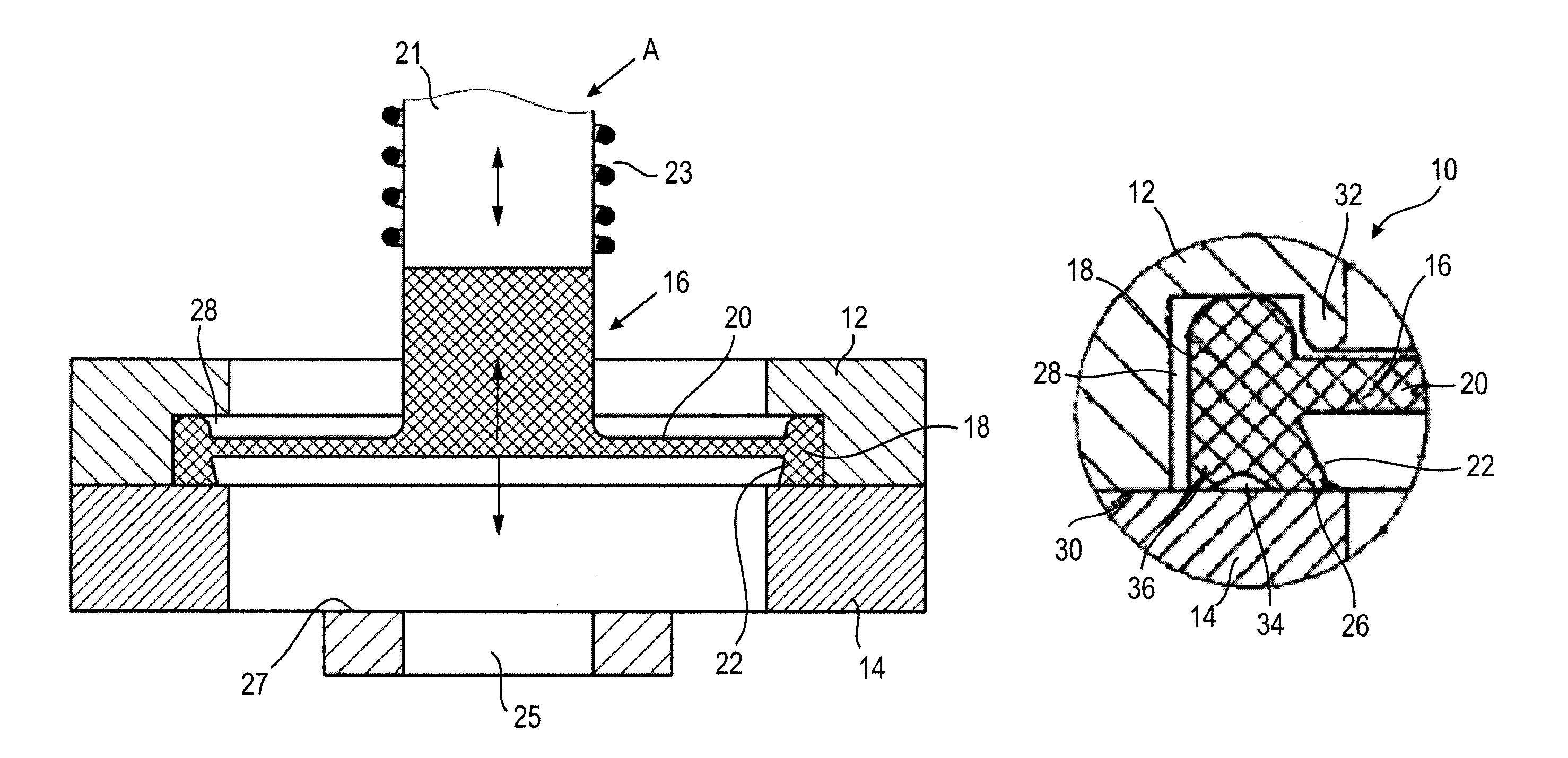
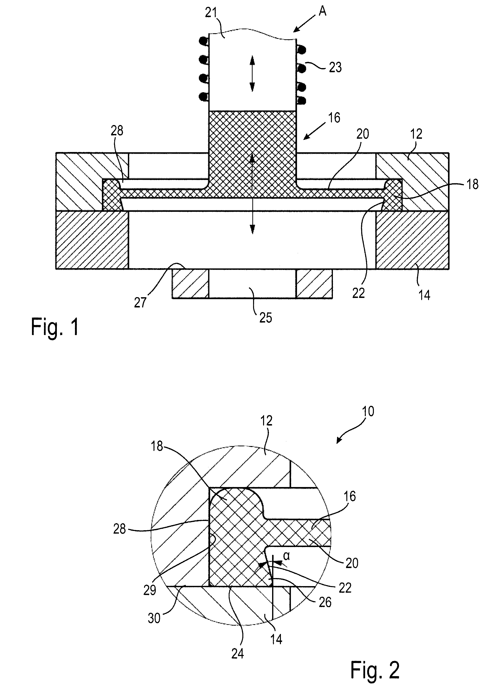
[0028]FIG. 1 illustrates a sectional view through a part of a valve housing 10 of a membrane valve comprising a first valve housing part 12, an adjoining second valve housing part 14 and a membrane 16 clamped therebetween.

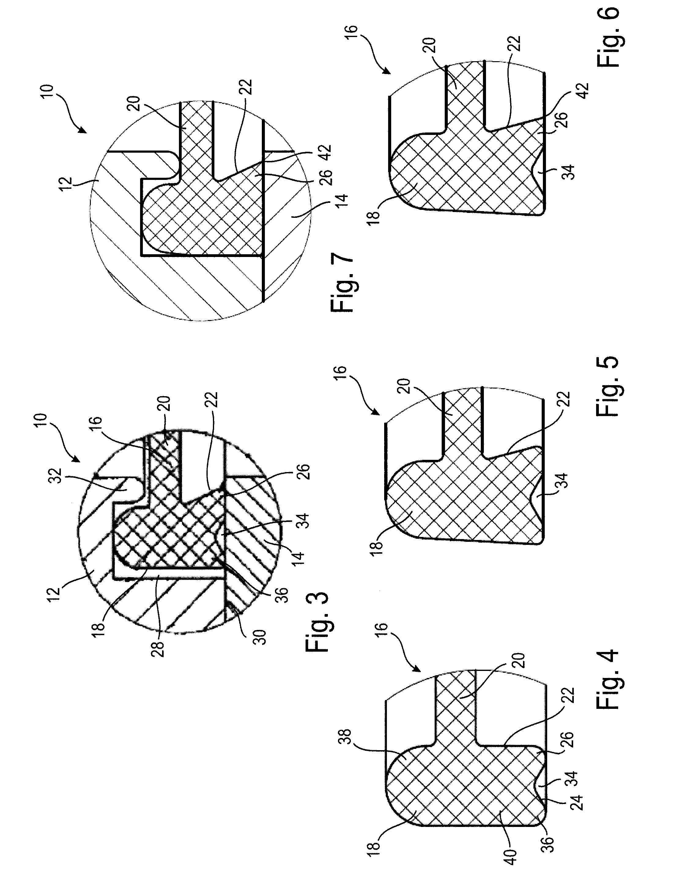
[0029]At its periphery, the membrane 16 comprises a surrounding bead 18 and an integrally adjoining, thin and plate-shaped membrane portion 20. The thin membrane portion 20 is flexible and can move in axial direction when acted upon with pressure.

[0030]The bead 18 is supported by the valve housing parts 12, 14.

[0031]The bead 18 axially protruding with respect to the portion 20 is provided with an undercut on a radial inner side 22.

[0032]The first valve housing part 12 is adjacent to an actuation unit A. On the side of the membrane 16 facing the actuation unit A, the membrane 16 is firmly connected to a valve actuation element (here of a magnetic armature) in known manner, the latter cooperating with the actuation unit A. The membrane 16 may be fastened to a magneti...


PUM


Abstract

A membrane valve comprising a first and a second valve housing part and a membrane clamped between the valve housing parts comprises a peripherally surrounding bead on the membrane and a thin, axially movable membrane portion adjacent thereto. The bead is supported by the two valve housing parts and is provided with an undercut at a radial inner side. Further, a membrane for installation in a membrane valve is provided.

Description

TECHNICAL FIELD[0001]The invention relates to a membrane valve as well as to a membrane for being installed in such a membrane valve.BACKGROUND OF THE INVENTION[0002]Membrane valves are known. They are frequently used in the field of analysis if a separation of the media is desired. This means that a fluid housing which is in contact with a medium is fluidically separated from an actuation unit by means of a membrane so that the medium is not able to find its way to the actuation unit. On a side facing away from the fluid housing, the membrane is connected to an actuation element which in turn cooperates with the actuation unit.[0003]It is also known to clamp the membrane between two housing parts. To this end, a contour such as e.g. a groove for receiving a membrane fastening portion is usually provided in each of the housing parts.[0004]In the process of manufacturing these membrane valves, the production of each of the contours entails an expenditure in terms of time and costs.[0...

Claims


Application Information

Patent Timeline
Patent Type & Authority Patents(United States)
IPC IPC(8): F16K7/14F16K41/10
CPCF16K41/103F16K7/14
Inventor BAUMANN, JOHANNESRIPSAM, CHRISTINASCHEIBE, RALFSCHWAB, HOLGER
Owner BURKERT WERKE
Why Eureka
Try Eureka