Conical laparoscopic apparatus for minimally invasive surgery

a laparoscopic and conical technology, applied in the field of laparoscopic surgery, can solve the problems of limiting the field of view, reducing depth perception, and rarely using multichannel devices, so as to reduce the chance of sealing bumping against one, increase the “fulcrum” (movement of the instrument tip), and remove the chance of sealing bumping

Inactive Publication Date: 2015-04-21
AXCESS INSTR IP HLDG CO
View PDF20 Cites 14 Cited by
  • Summary
  • Abstract
  • Description
  • Claims
  • Application Information

AI Technical Summary

Benefits of technology

[0028]The conduit extending through the anchor are “bored-out” or enlarged either preferably above the point in the anchor where it passes through the body or below the point. This allows the surgical instrument to freely move back and forth within the body (in a circular pattern) thereby increasing the “fulcrum” (movement of the instrument tip) within the body. In an alternate version the conical shapes of the conduit are combined into one cone which follows the outside conical shape of the anchor. A rubberized-malleable seal is placed within the cone or cones of the conduit and in one alternate the seals may be placed at the bottom (inside the patient) side of the anchor. The bottom placement of seals allows for more freedom of movement of the surgical instruments and removes the chance of seal bumping against one another.

Problems solved by technology

These narrow parallel channels have been found to limit the field of view and reduce depth perception.
Thus, multichannel devices have not met the needs of the surgical community and are rarely used.
The side crossing conduit will require that the central conduit be large; otherwise, a standard instrument would not be able to pass through the central conduit.
Such a device and method will result in fewer incisions for body access openings thus further decreasing the pain caused by surgery and further decreasing the recovery time and further reducing the risk of infection.
However, as their device was developed it was discovered that a perfectly round shape tended to swivel in the umbilicus and tended to lift out of the umbilicus in spite of the sutures.
It was discovered that if the shape of the anchor was modified to be oval in shape then the anchor would not as easily rotate.

Method used


Image

  • Conical laparoscopic apparatus for minimally invasive surgery
  • Conical laparoscopic apparatus for minimally invasive surgery
  • Conical laparoscopic apparatus for minimally invasive surgery

Examples


Embodiment Construction

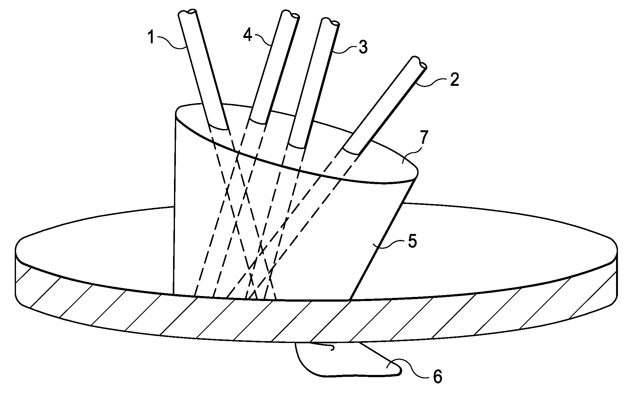
[0047]In reading this disclosure, the reader should understand that the term body flange generally means the entire device used to temporarily seal an incision in a patient. Thus, the body flange would include the body anchor—the section of the device that fits within the abdominal wall and is temporality sutured to the abdominal lining, any passageways extending through the body anchor (both above and below), any seals or other apparatus that is required to form the complete temporary entry closure.

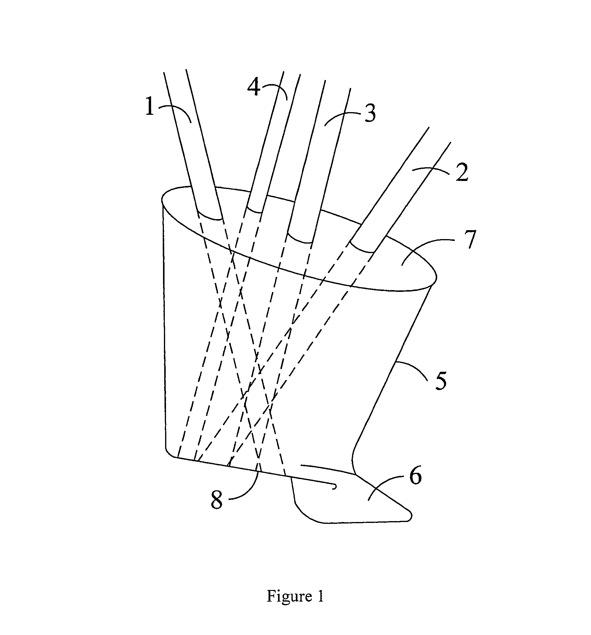
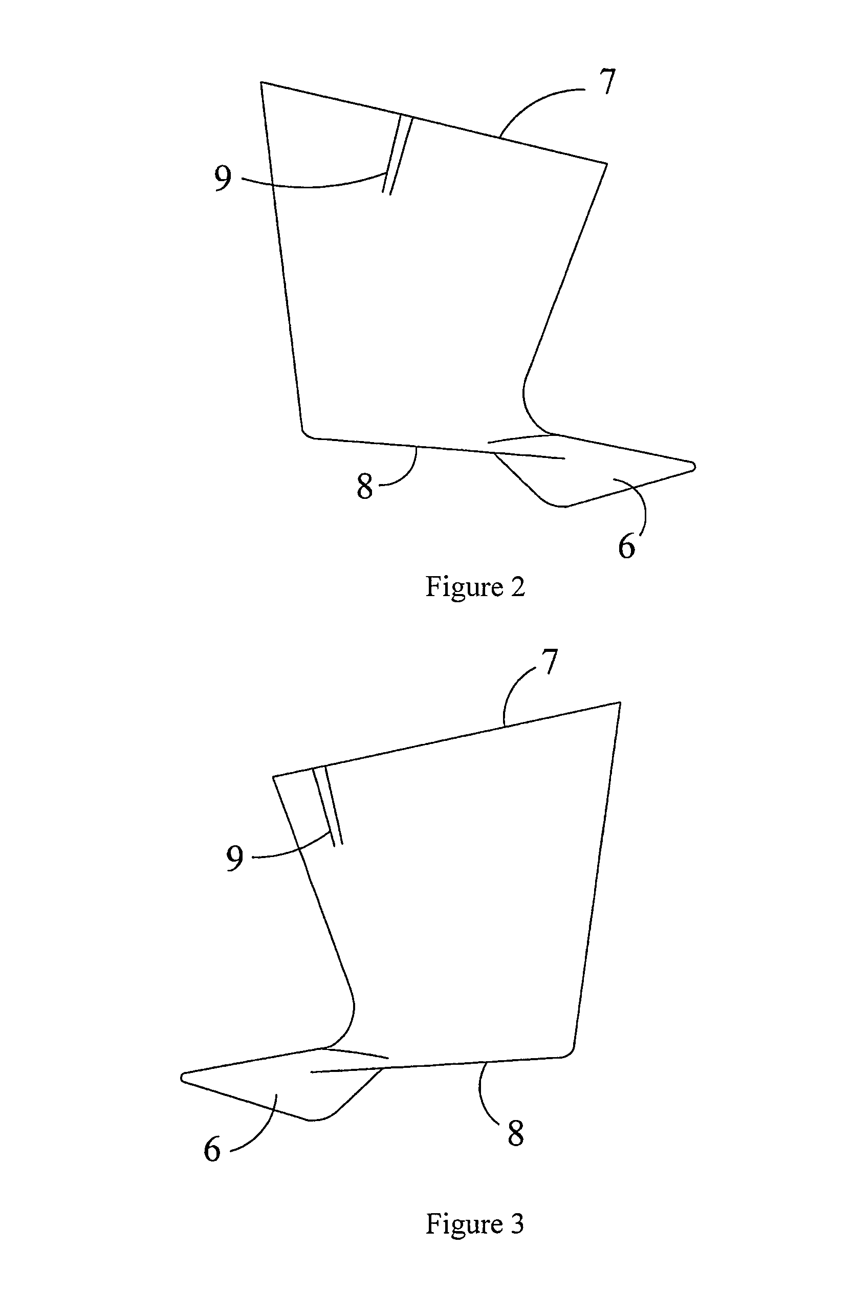
[0048]Turning now to FIG. 1, the improved body anchor is shown as item 5. The overall shape is somewhat like a boot, in that the upper perimeter, 7, and lower perimeter, 8 are elliptical. The anchor stabilizer, 6, extends from the lower perimeter following an axis which passes through the foci of the elliptical lower perimeter, 8. Crisscrossing instrument conduit, 1 and 2 are shown. It should be noted that these conduit need not crisscross to take advantage of the improved body anchor ut...


PUM


Abstract

A single body port or body flange access device having an oval shape and associated stabilizer anchor for performing laparoscopic surgery is disclosed. The device is slipped into the body anchor stabilizer first so that the anchor stabilizer lifts up fat and peritoneum inside the body thereby keeping the operating area clear and acting to hold the body flange in place. The device further has a plurality of crisscrossing conduits assuming the shape of a cone through which surgical instruments may be inserted. The instruments are manipulated so that triangulation is obtained using one patient body flange while standard surgical procedures are performed on the patient. Due the oval shape of the device, the device minimally rotates while instruments are manipulated.

Description

[0001]This application is a continuation-in-part of U.S. patent application Ser. No. 11 / 710,388 filed on Feb. 23, 2007 claiming the benefit of priority of U.S. Provisional Application Ser. No. 60 / 779,136, filed on Mar. 3, 2006, and further claims benefit of priority of U.S. Provisional Application 60 / 961,802, filed on Jul. 24, 2007, U.S. Provisional Application 60 / 965,404, filed on Aug. 20, 2007, and U.S. Provisional Application 61 / 124,066 filed on Apr. 14, 2008.TECHNICAL FIELD OF THE INVENTION[0002]This device and method relate to laparoscopic surgical procedures and in particular to an improved device and method for minimally invasive surgical procedures.BACKGROUND OF THE INVENTION[0003]Minimally invasive surgery has improved patient care by decreasing pain, shortening hospital stays, offering a faster recovery time and much smaller scars. In fact the surgical procedure is much shorter than standard procedures and offers less chance of infection, etc. These laparoscopic procedures...

Claims


Application Information

Patent Timeline
Patent Type & Authority Patents(United States)
IPC IPC(8): A61B1/313A61B1/018A61B17/34
CPCA61B17/3423A61B17/3421A61B17/3474A61B2017/3419A61B2017/3429A61B2017/3445A61B2017/3447A61B2017/3466A61B2017/3484A61B2017/3492
Inventor NORTON, MICHAEL J.ISCHY, NOEL D.
Owner AXCESS INSTR IP HLDG CO
Why Eureka
Try Eureka