Touch display panel and driving method thereof

a technology of display panel and driving method, which is applied in the direction of digital data processing details, instruments, electric digital data processing, etc., can solve the problems of inability to meet the demand of users for slim and small electronic products, inability to charge the display apparatus with simple display function, and relatively thick out-cell touch display panel. to achieve the effect of enabling charging time for display and touch control functions

Inactive Publication Date: 2015-04-21
HIMAX TECH LTD
View PDF9 Cites 8 Cited by
  • Summary
  • Abstract
  • Description
  • Claims
  • Application Information

AI Technical Summary

Benefits of technology

[0009]The present invention provides a driving method of a touch display panel which is capable of reducing the load between the touch electrode and the display electrode.
[0012]As described above, the electrode patterns of the touch display panel in the present invention are improved under the structure of the current display panel, so as to incorporate the touch control function into the display panel without disposing additional substrate. As the result, the touch display panel has the advantages of low cost and thinness. Further, by designing the third electrode patterns and the driving method, the interference of the touch scanning signals between the adjacent two groups is avoid, and the load between the touch electrode and the display electrode is reduced which provide sufficient charging time for display and touch control functions.

Problems solved by technology

Along with the development of the display technology and the demand of the multifunctional display apparatus, the display apparatus with simple display function is unable to fulfill the requirement of the users nowadays.
However, since the out-cell touch display panel is made by attaching two panels (including the display panel and the touch panel), and the two panels totally at least includes three layers of the substrates, the out-cell touch display panel is relatively thick, such that it is unable to comply with the demand of the user for a slim and small electronic product.
However, the load between the touch electrode and the display electrode of the current in-cell touch display panel is large, so it is hardly to provide enough charging time for display and touch control functions.

Method used


Image

  • Touch display panel and driving method thereof
  • Touch display panel and driving method thereof
  • Touch display panel and driving method thereof

Examples


Embodiment Construction

[0019]Reference will now be made in detail to the present preferred embodiments of the invention, examples of which are illustrated in the accompanying drawings. Wherever possible, the same reference numbers are used in the drawings and the description to refer to the same or like parts.

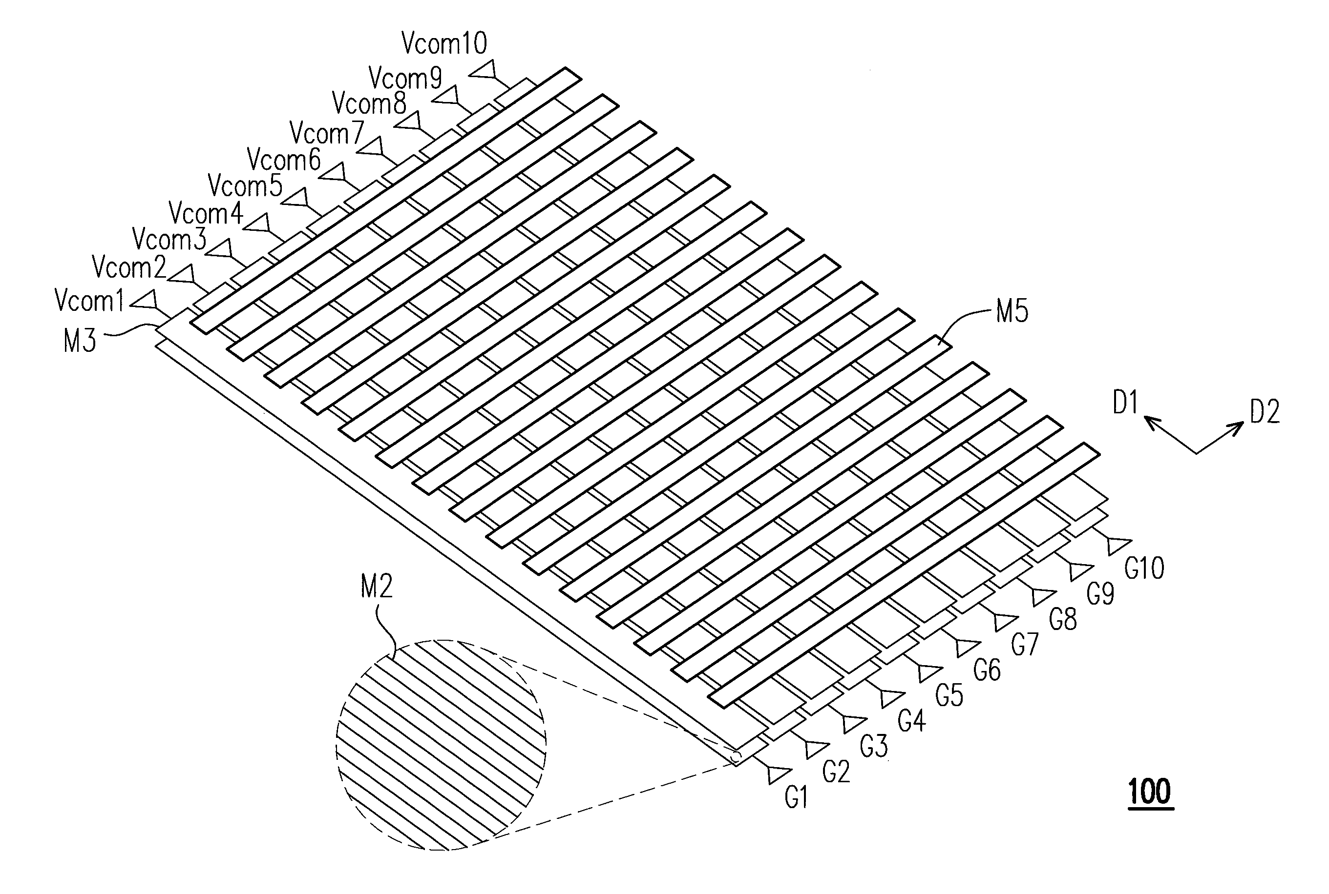
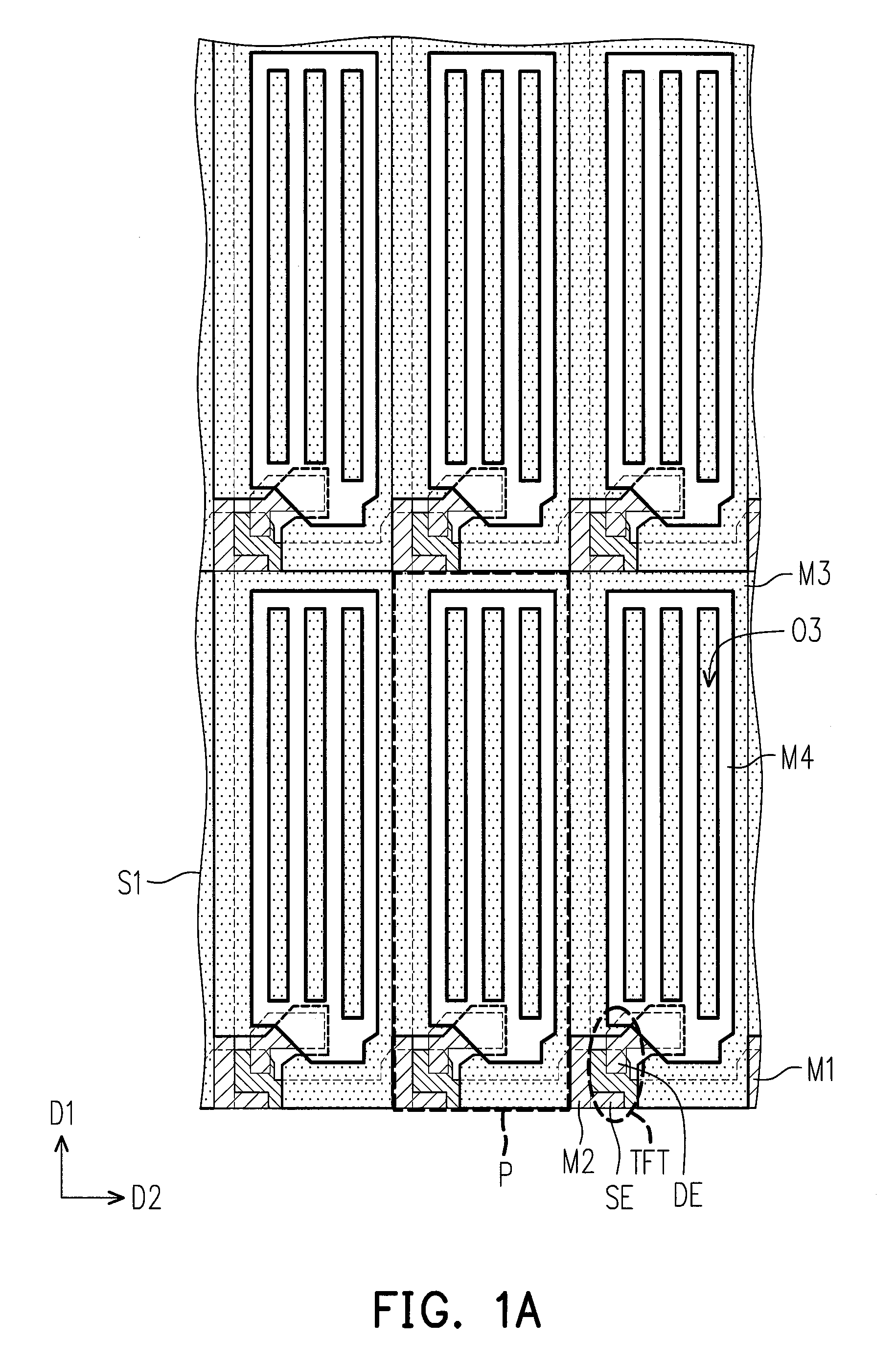
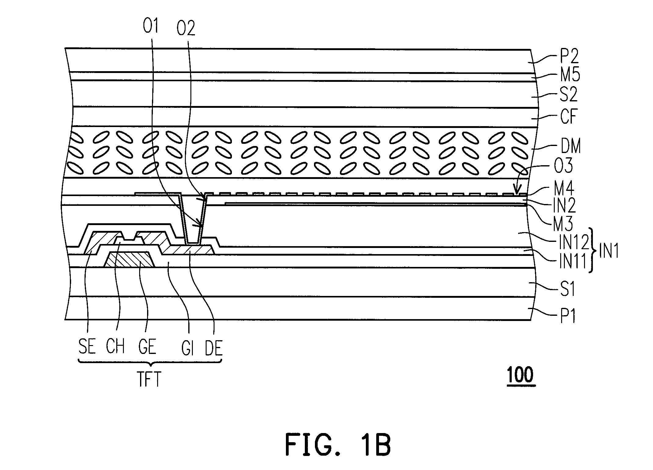
[0020]FIG. 1A is a partial top-view diagram of a touch display panel according to an embodiment of the present invention, where several film layers of the touch display panel are omitted in FIG. 1A for clearly showing the layer disposition of the electrode patterns on the first substrate. FIG. 1B is a cross-sectional diagram of a touch display panel according to an embodiment of the present invention. FIG. 1C is a side-view diagram of a touch display panel according to an embodiment of the present invention, where other film layers are omitted in FIG. 1C for clearly showing the layer disposition of the second electrode pattern, the fourth electrode pattern and the fifth electrode pattern.

[0021]Please...


PUM


Abstract

A touch display panel, including first electrode patterns, second electrode patterns, active elements, third electrode patterns and fourth electrode patterns is provided. The second electrode patterns and the first electrode pattern are set to form pixel areas. Each of the active elements is disposed in one of the pixel areas and electrically connected to the corresponding first electrode pattern and second electrode pattern. The third electrode patterns are arranged along a direction of an arrangement direction of the second electrode patterns and divide the second electrode patterns into groups, wherein each third pattern covers columns of the pixel areas. The fourth electrode patterns are electrically insulated to the third electrode patterns. Each fourth electrode pattern is disposed in one of the pixel areas and electrically connected to the corresponding active element. A driving method of a touch display panel is also provided.

Description

CROSS-REFERENCE TO RELATED APPLICATION[0001]This application claims the priority benefits of U.S. provisional application Ser. No. 61 / 834,855, filed on Jun. 13, 2013. The entirety of the above-mentioned patent applications is hereby incorporated by reference herein and made a part of this specification.BACKGROUND[0002]1. Field of the Disclosure[0003]The present disclosure generally relates to a display panel and a driving method thereof, and more particularly, to a touch display panel and a driving method thereof.[0004]2. Description of Related Art[0005]Along with the development of the display technology and the demand of the multifunctional display apparatus, the display apparatus with simple display function is unable to fulfill the requirement of the users nowadays. Therefore, a touch display panel has been proposed and put into practical use, where the touch function is incorporated into the display panel, so as to replace the external input apparatuses, such as keyboards and m...

Claims


Application Information

Patent Timeline
Patent Type & Authority Patents(United States)
IPC IPC(8): G06F3/041G06F1/16
CPCG06F3/0412G06F1/1643G06F3/0416G06F2203/04103G06F2203/04112G06F3/04166G06F3/0445G06F3/0446G06F3/044
Inventor HU, CHIA-WEICHANG, YAW-GUANGTAI, SHEN-FENGWU, WAI-PAN
Owner HIMAX TECH LTD
Why Eureka
Try Eureka