Viewing range notification method and TV receiver for implementing the same

a technology of viewing range and notification method, which is applied in the field of three-dimensional (3d) display devices, can solve the problems of not easy for viewers to check their current position, the viewer is preferable to come too close, and the elderly or children may experience difficulties in deciding and moving into the proper viewing position, so as to minimize the viewer's concentration loss, minimize fatigue, and maximize contrast

Inactive Publication Date: 2015-04-21
LG ELECTRONICS INC
View PDF20 Cites 0 Cited by
  • Summary
  • Abstract
  • Description
  • Claims
  • Application Information

AI Technical Summary

Benefits of technology

[0020]Firstly, the TV receiver may provide a guide message for guiding the viewer to change his or her current position if the viewer is not within an optimal viewing distance and viewing angle. This may allow the viewer to watch TV within an optimal viewing distance and an optimal viewing angle. Therefore, the viewer can watch 3D images provided from the 3D TV receiver at an optimal contrast and brightness with minimal fatigue. Furthermore, the viewer can acquire a proper viewing position based on a guide message provided from the TV receiver. This may minimize the viewer having to lose concentration due to the selection for an optimal position while watching TV, and may minimize user inconvenience. Especially, degradation in eyesight can be minimized for the elderly or children having a relatively low recognition capability.

Problems solved by technology

However, due to the recognition characteristics of human eyes, it is not preferable for the viewer to come too close to the screen.
This may cause the viewer to feel uncomfortable when viewing images and thus result in fatigue.
However, it is not easy for the viewer to check his or her current position and to adjust his position while viewing television.
Furthermore, while selecting a proper position, the viewer may not concentrate on the program being shown, or may such position re-alignment can cause inconvenience.
For example, the elderly or children may experience difficulties in deciding and moving into the proper viewing position.

Method used


Image

  • Viewing range notification method and TV receiver for implementing the same
  • Viewing range notification method and TV receiver for implementing the same
  • Viewing range notification method and TV receiver for implementing the same

Examples


second embodiment

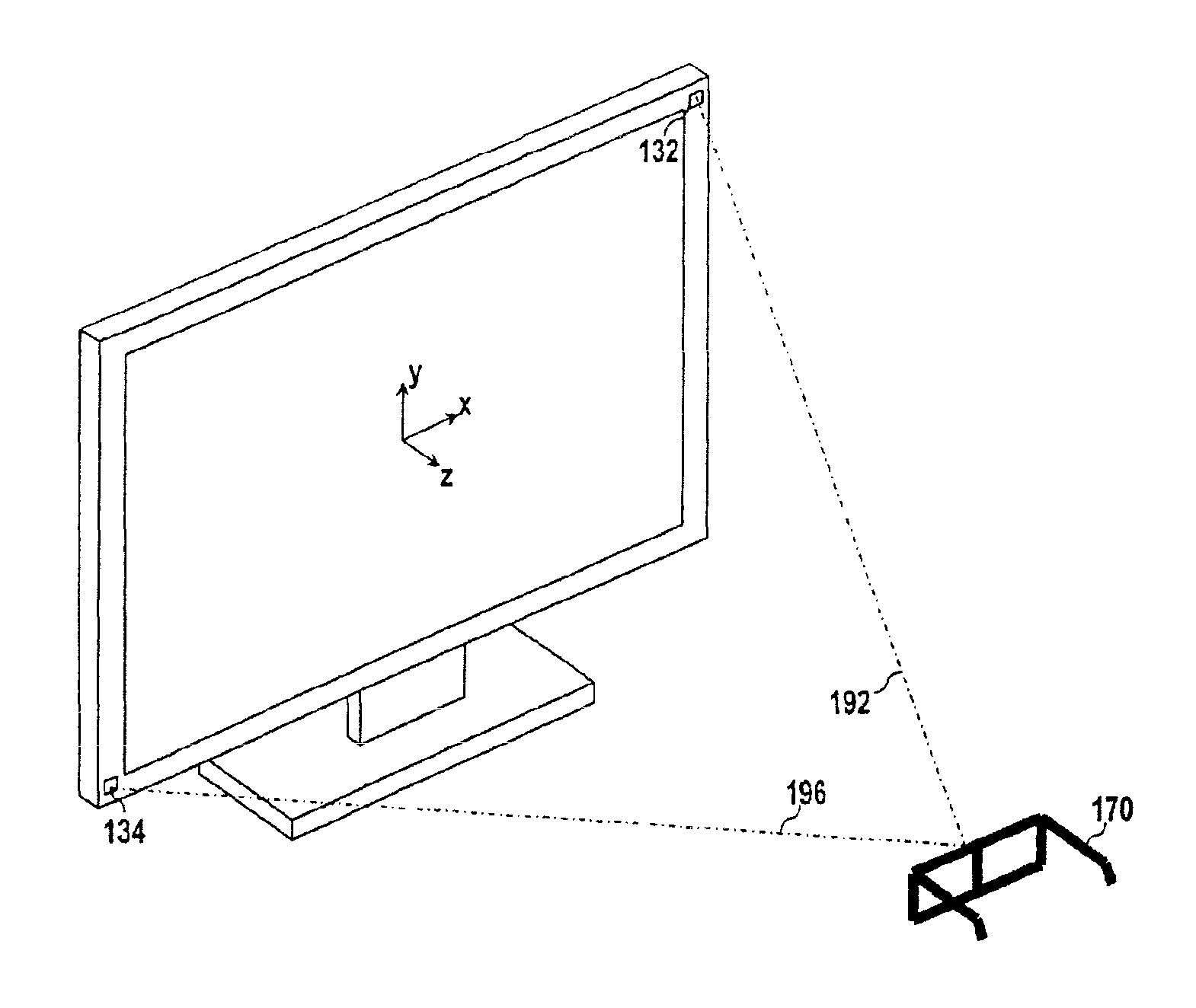
[0067]FIG. 10 is a block diagram of a TV receiver system according to the present disclosure. The TV receiver system of FIG. 10 is provided with a TV receiver 200 and polarized glasses 270. The TV receiver 200 is configured to receive a 3D broadcasting signal through terrestrial airwaves or a cable TV network, and to display a 3D image corresponding to the 3D broadcasting signal in a stereoscopic manner. A polarizing filter having polarizing directions different from each other by 90° is attached to a display panel of the TV receiver 200, thereby polarizing a left image and a right image in different directions. The polarized glasses 270 are provided with a polarized pattern in the same manner as that of the polarizing filter of the display panel. This may allow only a left image to be input to a viewer's left eye, and may allow only a right image to be input to a viewer's right eye.

[0068]Differently from that the TV receiver 100 of FIG. 3 is provided with the image sensors 132 and ...

third embodiment

[0077]FIG. 16 is a block diagram of a TV receiver system according to the present disclosure. The TV receiver system of FIG. 16 is provided with a TV receiver 300 and polarized glasses 370. The TV receiver 300 is configured to receive a 3D broadcasting signal through a terrestrial wave or a cable TV network, and to display a 3D image corresponding to the 3D broadcasting signal in a stereoscopic manner. A polarizing filter having polarizing directions different from each other by 90° is attached to a display panel of the TV receiver 300, thereby polarizing a left image and a right image to different directions. The polarized glasses 370 are provided with a polarization pattern in the same manner as the polarizing filter of the display panel. This may allow only a left image to be input to a viewer's left eye, and may allow only a right image to be input to a viewer's right eye.

[0078]The TV receiver 300 of this embodiment is provided with an ultrasonic transmitter 332, and three ultra...


PUM


Abstract

The present invention relates to a viewing range notification method for guiding a viewer to watch TV within an optimal viewing range by providing a guide message for advising the viewer to change his / her position if the viewer is out of the optimal viewing range and a TV receiver appropriate for implementing the guiding method. According to the present invention, the viewing range guiding method can be implemented by a three-dimensional TV receiver. The three-dimensional TV receiver determines whether the viewing range of the user is farther than a predetermined distance, and whether the viewing angle is within the predetermined angular range. Then, if the viewing range is nearer than the predetermined distance or the viewing angle is not within the predetermined angular range, the three-dimensional TV receiver provides a guide message for changing the viewing position.

Description

CROSS REFERENCE TO RELATED APPLICATIONS[0001]This application is the National Phase of PCT / KR2010 / 000120 filed on Jan. 8, 2010, which claims priority under 35 U.S.C. §119(e) to U.S. Provisional Application No. 61 / 187,642 filed on Jun. 16, 2009, all of which are hereby expressly incorporated by reference into the present application.TECHNICAL FIELD[0002]The present disclosure relates to a display device, and more particularly, to a three-dimensional (3D) display device. The present disclosure also relates to a user interface method in a 3D display device.BACKGROUND ART[0003]Generally, as a screen becomes wider, a viewer's angle of view can be implemented a various ways. Furthermore, the viewer can focus on an entire image, and can concentrate on the screen with a high sense of realism. Accordingly, demands for a large display device continuously increases. As techniques for manufacturing a large display device are developed, large and flat type display devices are being rapidly prese...

Claims


Application Information

Patent Timeline
Patent Type & Authority Patents(United States)
IPC IPC(8): H04N13/04H04N9/47H04N5/765H04N9/80H04N21/485
CPCH04N13/0475H04N13/0477H04N13/0429H04N21/485H04N13/376H04N13/332H04N13/373
Inventor CHOI, HAK-YOUNG
Owner LG ELECTRONICS INC
Why Eureka
Try Eureka