
Stationary apparatus for portable electronic device

a technology for electronic devices and stationary devices, which is applied in the direction of electric apparatus casings/cabinets/drawers, curtain suspension devices, instruments, etc., can solve the problems of user having to continuously hold a mobile phone in his or her hand, wrist or shoulder pain, and the problem of watching dmb tv or video clips using a wide screen has not been solved at all, so as to promote user convenience, simple manipulation, and attractive appearance. simple

Inactive Publication Date: 2015-04-21
LG ELECTRONICS INC
View PDF6 Cites 13 Cited by
  • Summary
  • Abstract
  • Description
  • Claims
  • Application Information

AI Technical Summary

Benefits of technology

[0020]An object of the present disclosure is to solve the foregoing problems, and an object of the present disclosure is to provide a withdrawable portable electronic device mounting apparatus for drawing a portable device mounting unit into the apparatus when the mounting unit is not used and drawing the portable device mounting unit out of the apparatus only when the mounting unit is used, thereby allowing the mount to be protruded on the outside only when used and the mount to be drawn in when not used to provide an elegant and simple appearance.
[0021]Another object of the present disclosure is to provide a withdrawable portable electronic device mounting apparatus in which a mounting unit is operated to be drawn in or out with a very simple manipulation, thereby promoting a user's convenience.
[0022]Still another object of the present disclosure is to provide a withdrawable portable electronic device mounting apparatus incorporated in a vehicle audio system in which the portable electronic device can be mounted while being drawn into or out of the interior with a very simple manipulation in the vehicle audio system.

Problems solved by technology

However, when the user watches DMB TV or video clips using a wide screen switched to a wide screen format, there is a drawback that the user has to continuously hold a mobile phone in his or her hand in the state of being positioned in the horizontal direction.
In other words, since an additional support means supporting a mobile phone is not provided on the mobile phone itself, the user should hold an edge of the mobile phone in his or her one or both hands in the state of being positioned in the horizontal direction while watching DMB TV or video clips with a wide screen, thereby causing wrist-ache or shoulder-ache when the user's hand is overstrained or in the worst case.
Moreover, while the user is not moving, a mobile phone should be held such that a screen of the mobile phone corresponds to the user's eye position when watching DMB TV or video clips using the mobile phone, thereby causing difficulties while watching DMB TV or video clips using the mobile phone.
Such mounts have been developed only with the emphasis on guiding the driver to safely drive a vehicle while using a mobile phone during driving, and thus problems caused while watching DMB TV or video clips using a wide screen have not been solved at all.
However, as a structure for mounting a mobile phone on the mounting unit is mounted by a magnet, a steel plate corresponding to a magnetic force of the magnet provided at the mounting unit should be provided at the mobile phone, thereby having a problem that an external appearance of the mobile phone cannot be elegantly accomplished by the steel plate.
Such an adverse effect on an external appearance of the mobile phone, which is exhibited by further providing a steel plate as described above, may be easily disapproved and thus cannot be widely utilized by users who desired to elegantly or simply provide the appearance of the mobile phone.
Moreover, according to the related art, a mount for mounting a mobile phone may be configured to be placed and used between a user's shoulder and face to allow the user to freely use his or her both hands and write a memo or perform other tasks while making a phone call, thereby having problems caused when watching DMB TV or video clips using a wide screen of the mobile phone as described above.
In particular, when a mounting apparatus is provided in the state of being externally exposed in a limited small space such as the interior of a vehicle, the relevant mounting apparatus may be formed of various shapes, and in this case, the mounting apparatus may be protruded when installed as a separate device, thereby having a problem of causing poor appearance and damage when not being used.
Furthermore, the mobile phone mount may be obstructed from the outside or collided with other devices, thereby having a problem of causing damage to those devices.

Method used


Image

  • Stationary apparatus for portable electronic device
  • Stationary apparatus for portable electronic device
  • Stationary apparatus for portable electronic device

Examples


Embodiment Construction

[0073]Hereinafter, a withdrawable portable electronic device mounting apparatus according to a preferred embodiment of the present disclosure will be described in detail with reference to the accompanying drawings.

[0074]Prior to the description, it should be noted that terms and words used in the description and claims must not be limited and interpreted to be typical or literal, and should be construed as the meaning and concept conforming to the technical concept of the invention on the basis that the inventor can define the concept of the terms and words to describe the invention in a best way.

[0075]Accordingly, since the embodiments described in the present invention and configurations shown the drawings are the most preferred embodiments only and do not represent all of technical concept of the invention, it should be understood that there may be various equivalents and modification examples that may replace them at the time of application of present invention.

[0076]Hereinafter...


PUM


Abstract

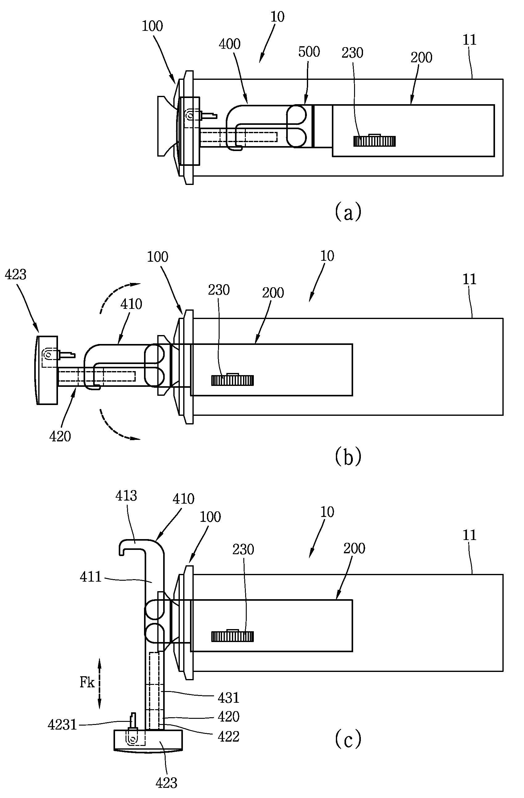
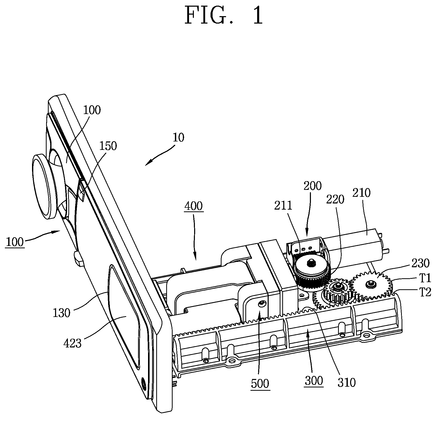
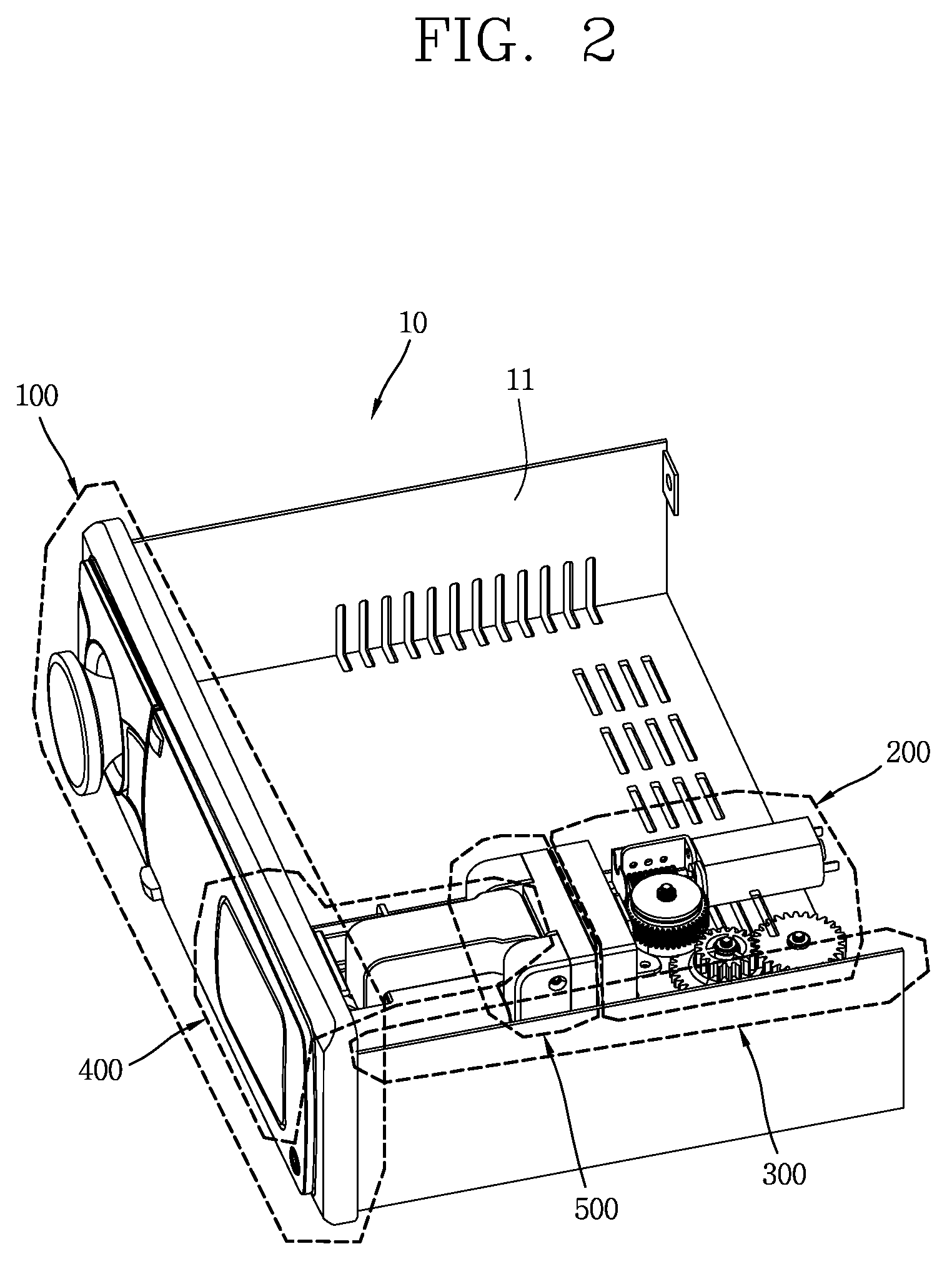
A withdrawable portable device mounting apparatus is provided in a vehicle audio system, in which a mount capable of mounting a portable electronic device is drawn out using an electromotive force with a very simple manipulation by pressing a drive button or the like. The apparatus may include a case, a front panel provided at a front surface of the case to have a control panel, a mounting unit loading hole, and a loading button, a drive unit configured to drive a mounting unit through a mounting unit loading hole of the front panel in a withdrawable manner, a loading unit mutually operated with the drive unit to allow the mounting unit to be drawn in or out, and a mounting unit inserted into the front panel in a folded state during a drawing-in operation, and unfolded through the mounting unit loading hole during a drawing-out operation.

Description

CROSS-REFERENCE TO RELATED APPLICATIONS[0001]The present disclosure relates to subject matter contained in preliminary U.S. application Ser. No. 61 / 507,815, filed on Jul. 14, 2011, which is herein expressly incorporated by reference in its entirety.BACKGROUND OF THE INVENTION[0002]1. Field of the Invention[0003]The present disclosure relates to a withdrawable portable device mounting apparatus provided in an vehicle audio system, and more particularly, to a withdrawable portable device mounting apparatus in which a mount capable of mounting a portable electronic device is drawn out using an electromotive force with a very simple manipulation by pressing a drive button or the like such that an upper and a lower mounting member are unfolded in the vertical direction by a torsion spring to mount a portable electronic device, and the mount is automatically drawn in while the upper and the lower mounting member are folded during the drawing-in operation.[0004]2. Description of the Relate...

Claims


Application Information

Patent Timeline
Patent Type & Authority Patents(United States)
IPC IPC(8): H04R1/02B60R11/00B60R11/02
CPCB60R11/02B60R11/0241B60R2011/0082B60R2011/0092B60R2011/0005B60R2011/0071B60R2011/0085
Inventor HUH, BYUNGMUKIM, KYOUNGJOUNGCHONG, YUONUI
Owner LG ELECTRONICS INC
Learn More