
Generating functional artifacts from low level design diagrams

a technology of functional artifacts and design diagrams, applied in the field of software development, can solve the problems of software reuse, less margins, and lower quality, and achieve the effect of reducing the cost of software development, reducing the cost of development, and improving the quality of the work

Inactive Publication Date: 2015-04-21
INT BUSINESS MASCH CORP
View PDF7 Cites 6 Cited by
  • Summary
  • Abstract
  • Description
  • Claims
  • Application Information

AI Technical Summary

Benefits of technology

The patent text explains that by reusing existing assets instead of creating new services from scratch, it can significantly reduce the development time for projects. Additionally, the text explains that this approach also increases reusability, meaning that it takes less time to achieve the desired functional capabilities. Overall, this approach improves efficiency and productivity in software development.

Problems solved by technology

However, most organizations do not take advantage of this similarity and conduct each project from scratch, leading to lesser margins and lower quality.
Software reuse is a significant issue for a large part of the information technology (IT) business involved with the development of custom software solutions.

Method used


Image

  • Generating functional artifacts from low level design diagrams
  • Generating functional artifacts from low level design diagrams
  • Generating functional artifacts from low level design diagrams

Examples


example domain

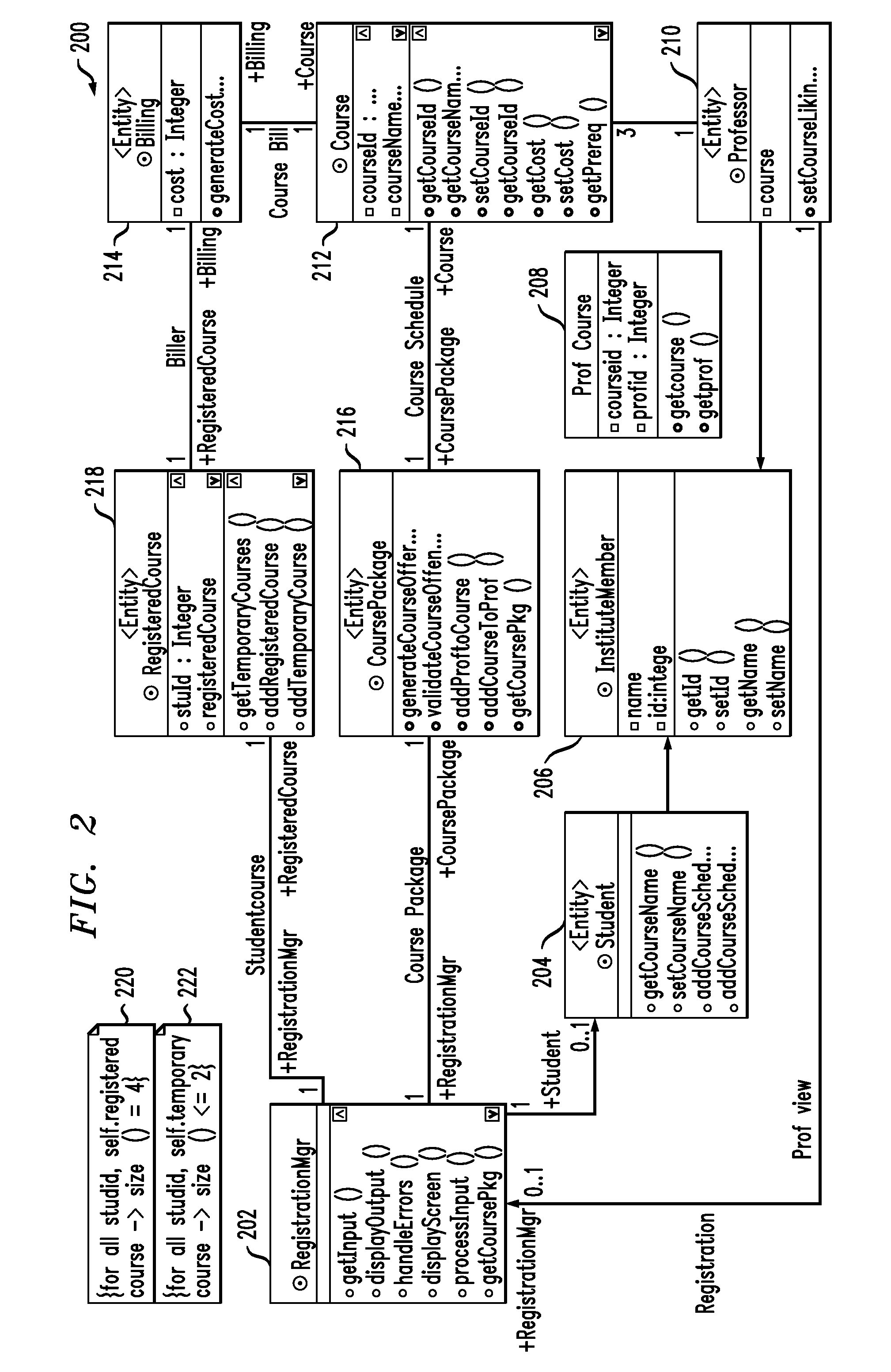
[0045]Purely by way of example and not limitation, a case study of student course registration taken from the Rational tutorial will be employed as the running example in the exemplary embodiment. In this non-limiting example:

[0046](a) Each semester, students may request a course catalogue containing a list of course offerings for the semester.

[0047](b) The new on-line registration system will allow students to select four course offerings and two alternative choices for the coming semester.

[0048](c) No course offering will have more than ten students and less than three students.

[0049](d) Billing is done for each student for the courses registered.

[0050](e) Professors must be able update their course offerings and see which students signed up.

[0051]For the purpose of experimentation and evaluation, in this application, several solutions for the above problem are illustrated. FIG. 2 gives the UML class diagram 200 for an exemplary solution, henceforth referred to as “Solution A” (So...


PUM


Abstract

At least one design diagram is obtained from at least one previous software project. At least one service abstraction is extracted from the at least one design diagram. The at least one service abstraction is reused in a new software project. In another aspect, requirements are obtained for a current software project; at least one class diagram is obtained from at least one previous software project; a dependency graph is generated from the at least one design diagram, using link analysis; relationships between classes in the dependency graph are analyzed to obtain functional artifacts for the requirements; and the functional artifacts are reused in the new software project.

Description

FIELD OF THE INVENTION[0001]The present invention relates to the electrical, electronic and computer arts, and, more particularly, to software development and the like.BACKGROUND OF THE INVENTION[0002]In custom software development projects, in general, the same type of software is being built for different customers. The deliverables are similar because they address the same market (e.g., telecommunications, banking, and so on) or have similar functions, or both. However, most organizations do not take advantage of this similarity and conduct each project from scratch, leading to lesser margins and lower quality.[0003]Software reuse is a significant issue for a large part of the information technology (IT) business involved with the development of custom software solutions. Most organizations build software solutions for focused markets, also called business lines, verticals or domains, and they seek to grow their expertise with every project.SUMMARY OF THE INVENTION[0004]Principle...

Claims


Application Information

Patent Timeline
Patent Type & Authority Patents(United States)
IPC IPC(8): G06F9/44
CPCG06F8/10G06F8/36
Inventor KANNAN, KALAPRIYABHAMIDIPATY, ANURADHASRIVASTAVA, BIPLAV
Owner INT BUSINESS MASCH CORP
Learn More