Debris handling apparatus for a vacuum cleaner

a vacuum cleaner and dust handling technology, applied in the direction of separating, cleaning filter means, separation processes, etc., can solve the problems of affecting the work efficiency of workers and vacuum equipment, and affecting the efficiency of vacuum equipment, so as to facilitate the transfer of particulates and prevent the effect of pneumatic flow

Active Publication Date: 2015-04-28
CHRISTY
View PDF12 Cites 12 Cited by
  • Summary
  • Abstract
  • Description
  • Claims
  • Application Information

AI Technical Summary

Benefits of technology

[0007]In another embodiment of the invention, a debris handling apparatus facilitates transfer of particulates collected in the vacuum cleaner hopper directly into a disposable bag rather than into a dump tank. In the disposable bag embodiment, as with the dump tank embodiment, the discharge valve is operable between the first position in which the discharge chute of the hopper is closed to pneumatic flow and the second position in which the discharge chute of the hopper is open to pneumatic flow. But, in the disposable bag embodiment, a duct has an inlet end contoured to contain the discharge end of the hopper discharge chute. The duct is sized to provide an air passage between the outside wall of the chute and the inside wall of the duct. The duct has an outlet end contoured to be inserted into the mouth of the bag. The inside wall of the mouth of the bag is held against the outside wall of the duct so as to prevent pneumatic flow between the bag and the duct. This can be accomplished, for example, by resiliently stretching an elastic band to gird the duct inlet end with the mouth of the bag between the duct and the elastic band. In this configuration, ambient air is drawn through the air passage between the hopper discharge chute and the duct, so the bag is not collapsed by the operation of the vacuum cleaner.

Problems solved by technology

Therefore, these vacuum systems are always shut down before the dump tank or bag is removed and remain out of service until the dump tank or a new bag is reconnected.
The down time for workers and vacuum equipment while tanks are emptied or bags are replaced can be a considerable proportion of a work day.

Method used


Image

  • Debris handling apparatus for a vacuum cleaner
  • Debris handling apparatus for a vacuum cleaner
  • Debris handling apparatus for a vacuum cleaner

Examples


Embodiment Construction

[0024]Turning first to FIGS. 1 and 7, a vacuum cleaner 10 is illustrated which incorporates a dual storage dust collector 11. The vacuum cleaner 10 has a chassis 13 with a pair of rear wheels 15 for moving the vacuum cleaner 10 to and from areas to be vacuumed and two casters 17 which allow the vacuum cleaner 10 to roll and change direction during vacuuming.

[0025]A platform 21 which rolls on four casters 23 onto and from the chassis 13 of the vacuum cleaner 10 supports the lower portion 25 of the dust collector 11. The lower portion 25 of the dust collector 11, as shown, includes a cylindrical dump tank 27 with an open top 29 and a pair of diametrically opposed cam-over clamps 31.

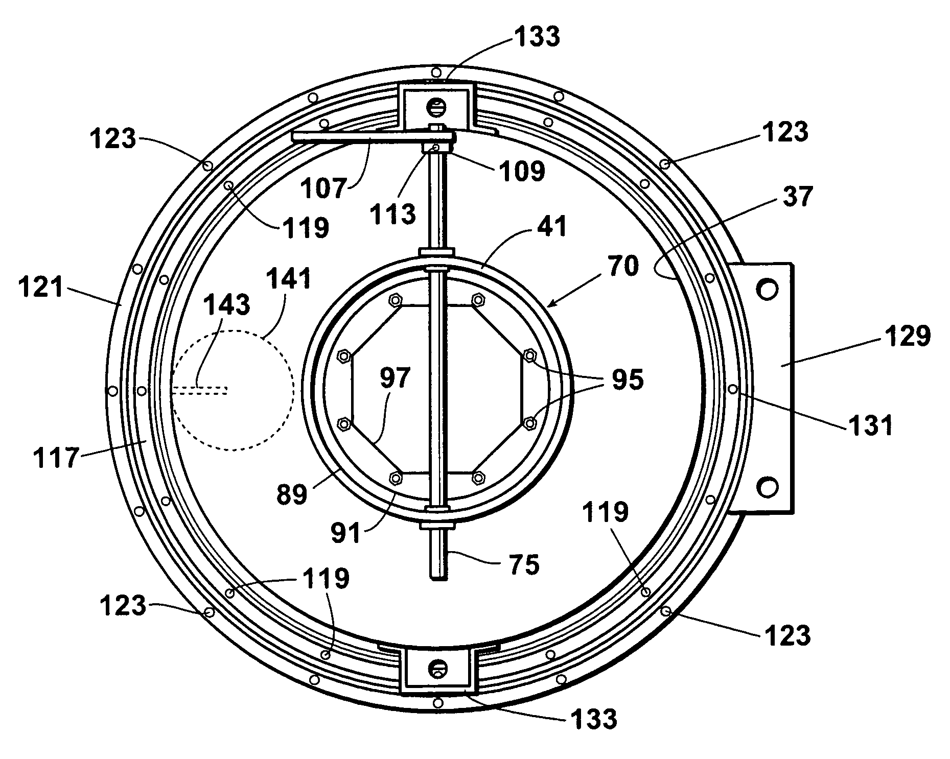
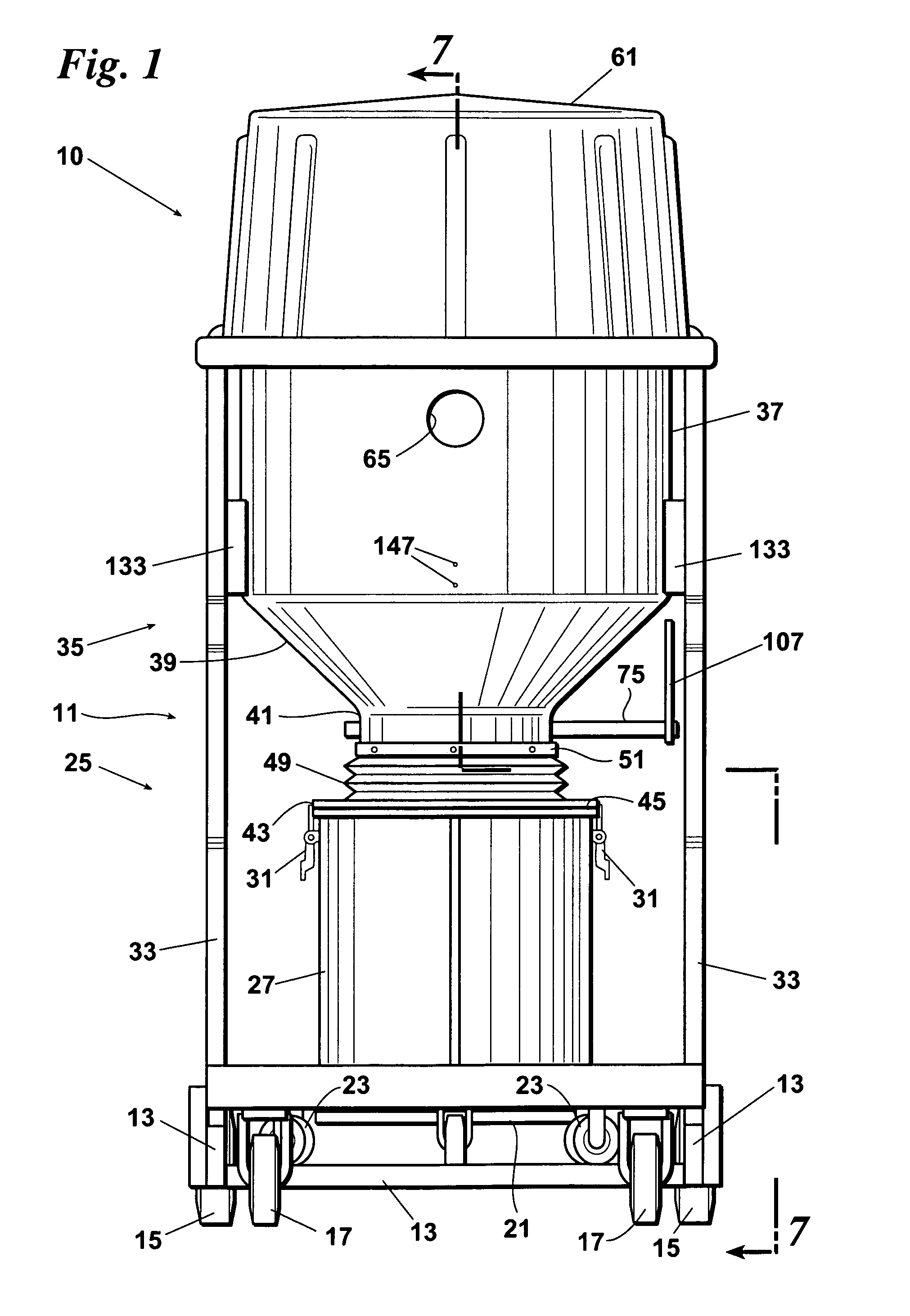
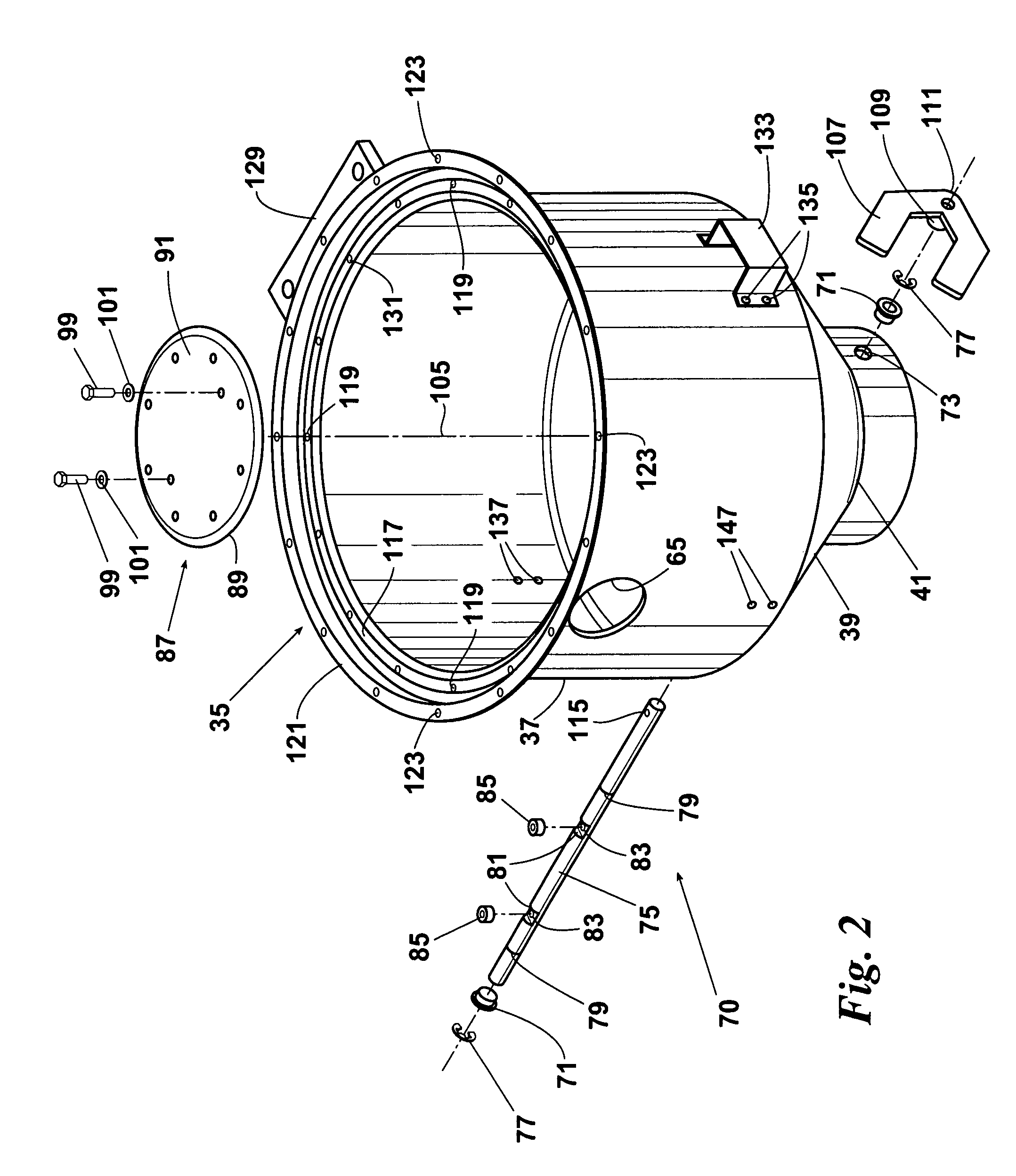
[0026]A frame 33 extending upwardly from the chassis 13 supports the upper portion 35 of the dust collector 11. The upper portion 35 of the dust collector 11 includes a barrel 37, a hopper 39 and a neck 41. The barrel 37 extends downwardly to the hopper 39 which in turn extends downwardly to the neck 41.

[00...


PUM

PropertyMeasurementUnit
threshold quantityaaaaaaaaaa
weightaaaaaaaaaa
pressureaaaaaaaaaa

Abstract

A dual storage dust collector for a vacuum cleaner has a hopper for receiving the dust from the vacuum and a dump tank for receiving the dust from the hopper. A valve between the hopper and the dump tank is operable whether or not the vacuum is running. Thus, whenever the valve is open, dust falls from the hopper into the dump tank and, whenever the valve is closed, the dump tank can be disconnected from the hopper and emptied without interruption of the vacuuming process. In another embodiment, the dump tank can be replaced by a disposable bag filled directly from the valve.

Description

REFERENCE TO PENDING APPLICATION[0001]This application is a continuation-in-part application claiming priority to U.S. patent application Ser. No. 11 / 655,505 filed Jan. 19, 2007.BACKGROUND OF THE INVENTION[0002]This invention relates generally to vacuum cleaning systems and more particularly concerns dual storage dust collectors used with many such systems.[0003]Presently, an upper hopper and lower dump tank or disposable bag are separated by a flapper or gate pivoting on an offset axis with a weight below one side of the axis. The hopper and tank or bag taken together form a single sealed container with the flapper between the tanks. While the hopper and the tank or bag are connected, they are at equalized pressure and the weight tends to hold the flapper closed so that collected dust settles on the closed flapper. When the collected dust overcomes the weight, the flapper drops to deposit settled dust into the dump tank or bag. When sufficient dust has fallen to allow the weight to...

Claims


Application Information

Patent Timeline
Patent Type & Authority Patents(United States)
IPC IPC(8): B01D45/18A47L9/12A47L9/16A47L9/20
CPCB01D45/18A47L9/125A47L9/1683A47L9/20
Inventor VEMURI, SHANTI K.
Owner CHRISTY
Why Eureka
Try Eureka