Tri-fin TCAS antenna

a technology of collision avoidance system and antenna, which is applied in direction finders using radio waves, instruments, and reradiation, etc., can solve the problems of increased drag, unsuitable use, and serious drag created by the antenna, and achieves low drag characteristics and less expensive manufacture.

Inactive Publication Date: 2015-04-28
ROCKWELL COLLINS INC
View PDF8 Cites 10 Cited by
  • Summary
  • Abstract
  • Description
  • Claims
  • Application Information

AI Technical Summary

Benefits of technology

[0008]One embodiment of the present invention is a TCAS antenna having four directional antenna arrays in a tri-fin antenna housing. Directional antenna arrays are less expensive to manufacture than traditional folded monopole antenna for a TCAS application. In addition, the tri-fin antenna housing provides low drag characteristics.

Problems solved by technology

Because TCAS antennas are attached to the exterior surface of an aircraft, drag created by the antenna is a serious concern.
Because TCAS antennas generally operate in a very narrow band, such antennas are not suitable for use by other L band radios operating outside that narrow band.
Additional antennas and associated cables may cause additional drag, consume power, add weight and add cost.

Method used


Image

  • Tri-fin TCAS antenna
  • Tri-fin TCAS antenna
  • Tri-fin TCAS antenna

Examples


Embodiment Construction

[0016]Reference will now be made in detail to the subject matter disclosed, which is illustrated in the accompanying drawings. The scope of the invention is limited only by the claims; numerous alternatives, modifications and equivalents are encompassed. For the purpose of clarity, technical material that is known in the technical fields related to the embodiments has not been described in detail to avoid unnecessarily obscuring the description.

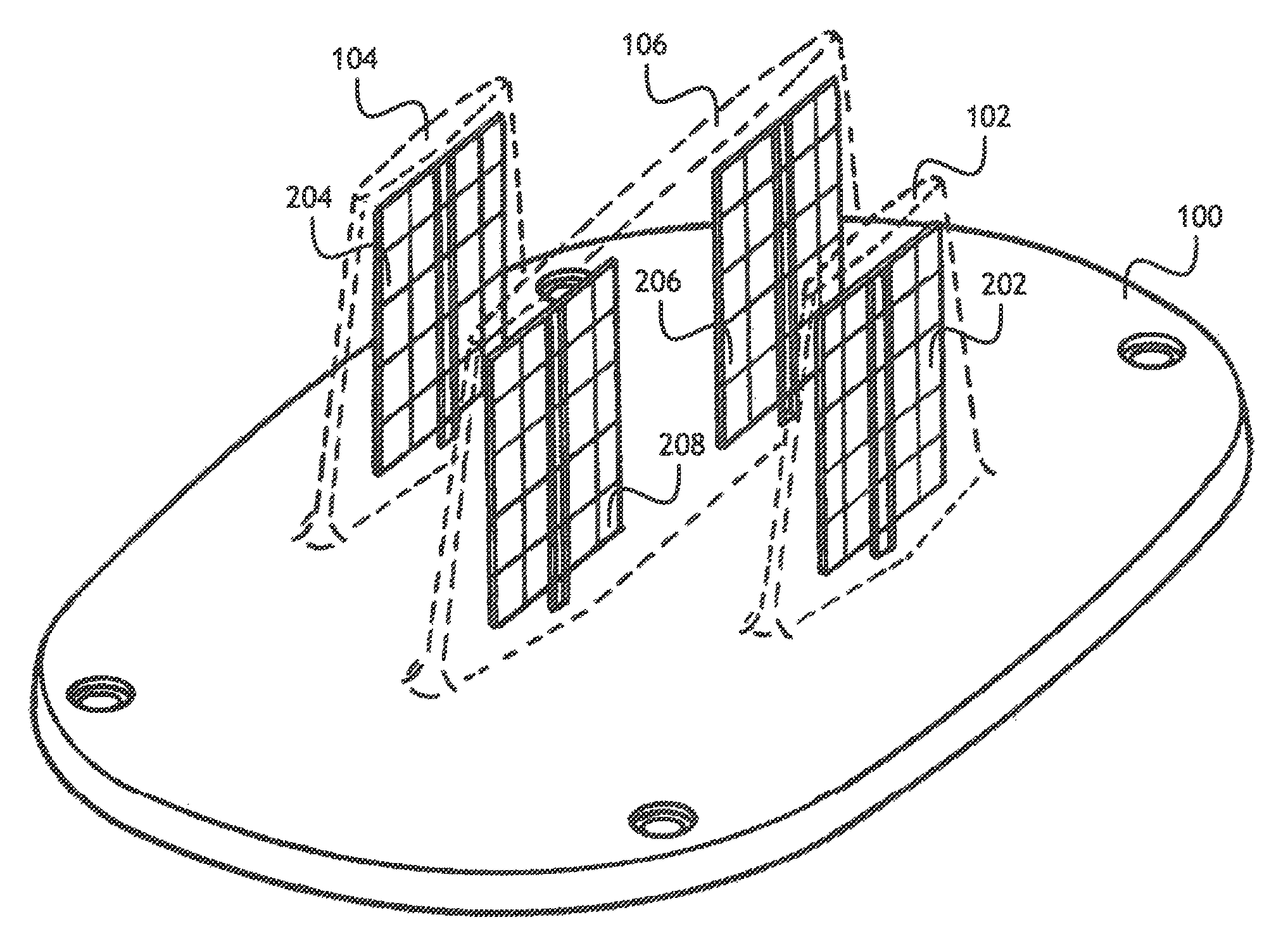
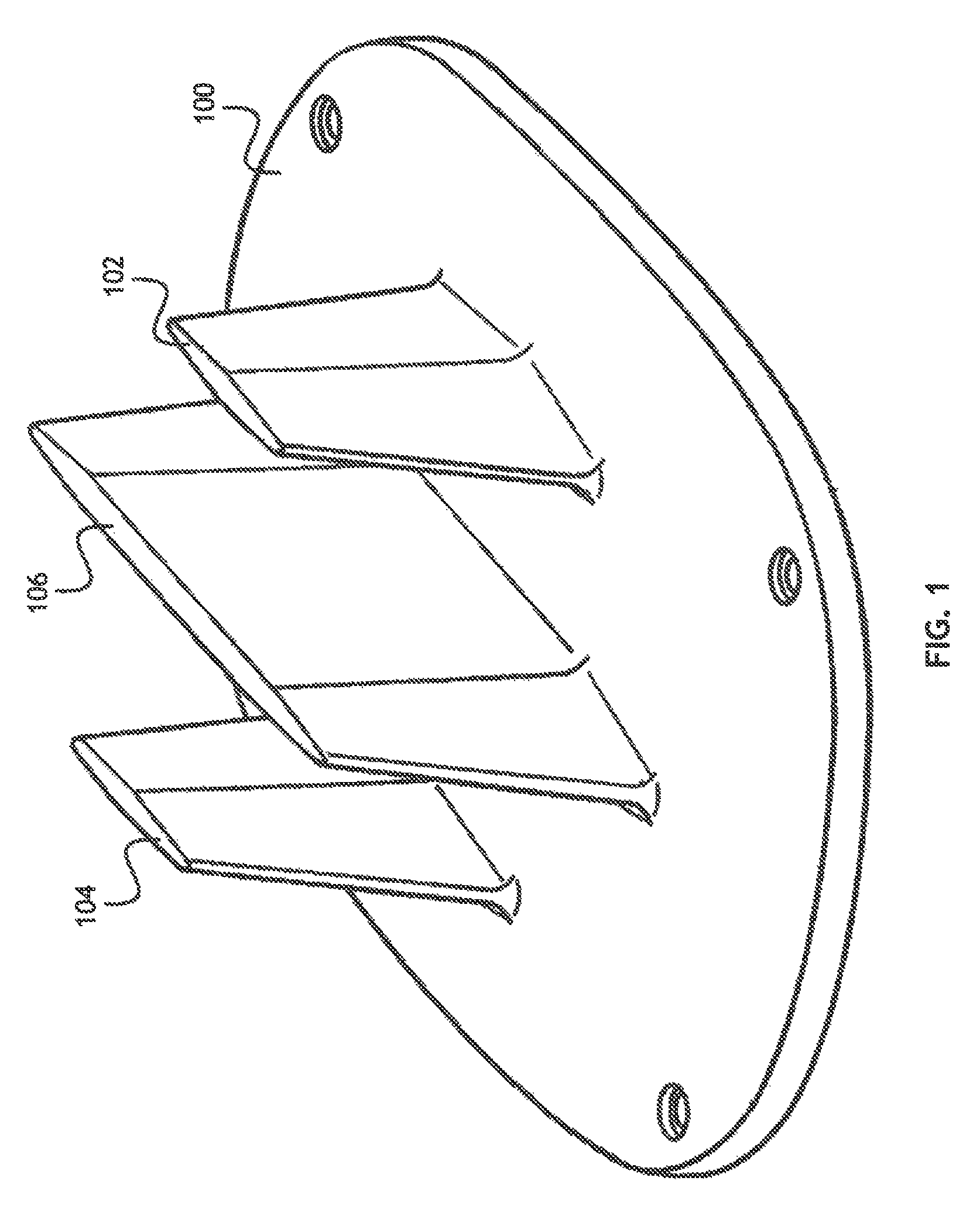
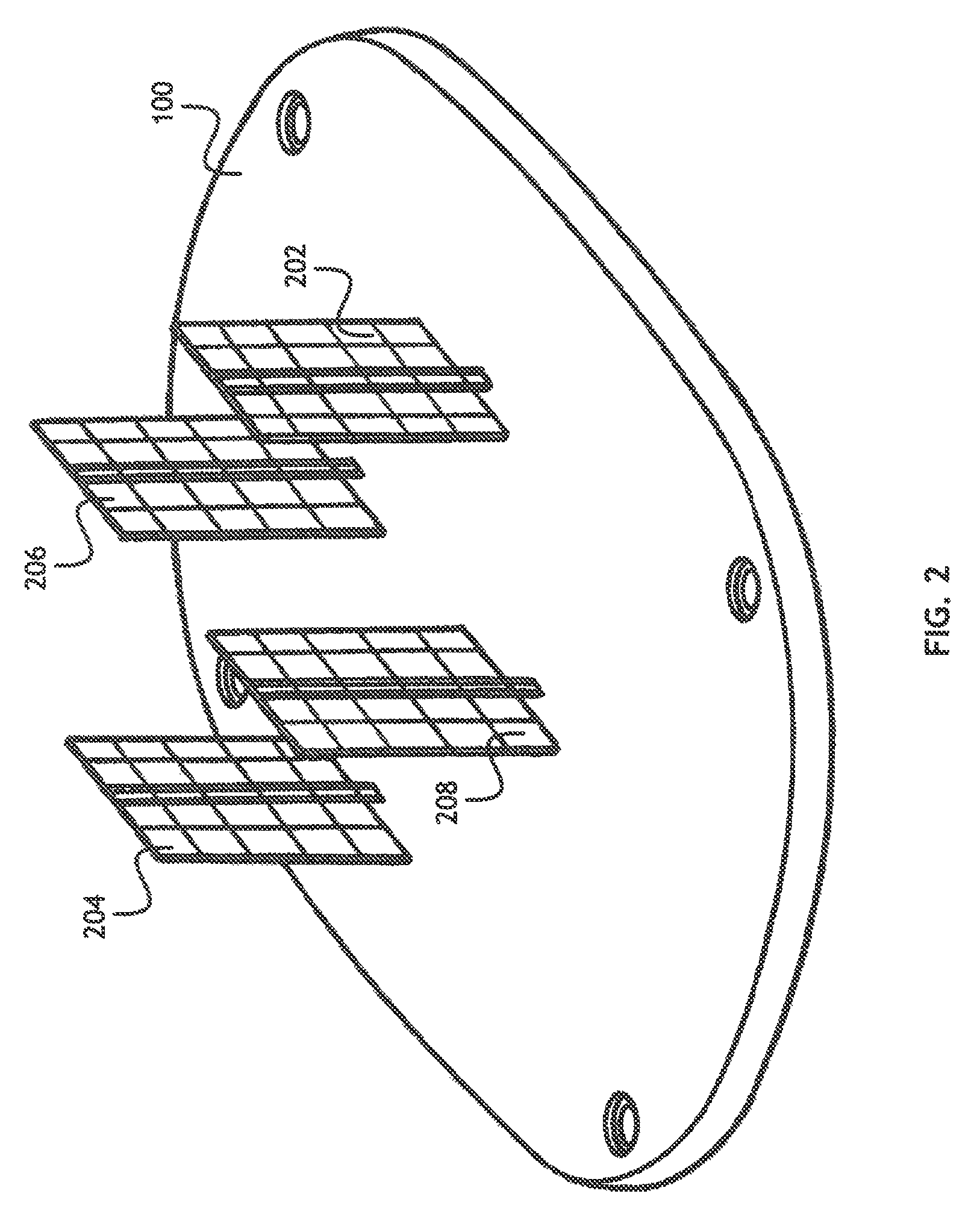
[0017]Referring to FIG. 1, an antenna housing is shown. The antenna housing may include a base 100. The base 100 may be configured to occupy the same area on the surface of an aircraft (“footprint”) as prior art TCAS antennas. The antenna housing may also include three fins 102, 104, 106. The fins 102, 104, 106 may extend perpendicularly from the base 100, and be substantially parallel to each other. The fins 102, 104, 106 may be oriented in the direction of travel of an aircraft to provide the minimum possible drag. Each of the fins 102, 104...


PUM


Abstract

A low drag TCAS antenna includes a plurality of broadband antenna elements in a housing having at least three fins. L band radios in the aircraft may utilize the broadband antenna elements, thereby reducing power consumption, cost and aerodynamic inefficiency due to a plurality of antennas protruding from the aircraft.

Description

FIELD OF THE INVENTION[0001]The present invention is directed generally toward traffic collision avoidance system (TCAS) antennas, and more particularly toward TCAS antennas configured for broadband operation.BACKGROUND OF THE INVENTION[0002]A traffic collision avoidance system (TCAS) is an aircraft collision avoidance system designed to reduce the incidence of mid-air collisions between aircraft. TCAS monitors the airspace around an aircraft for other aircraft equipped with a corresponding active transponder, independent of air traffic control, and warns pilots of the presence of other transponder-equipped aircraft which may present a threat of mid-air collision.[0003]The antennas used by TCAS may include a directional antenna mounted on the top of the aircraft and a directional or omnidirectional antenna on the bottom of the aircraft. This antenna may enable a transponder to receive interrogations at 1030 MHz and reply to the received interrogations at 1090 MHz.[0004]Because TCAS ...

Claims


Application Information

Patent Timeline
Patent Type & Authority Patents(United States)
IPC IPC(8): H01Q1/28G01S13/933G01S3/02
CPCG01S13/9303G01S3/023H01Q1/28H01Q1/42H01Q9/40H01Q21/205G01S13/933
Inventor BILLSBERRY, MARKMASON, SHAWN
Owner ROCKWELL COLLINS INC
Why Eureka
Try Eureka