Droplet discharge head, and image forming apparatus

a technology of droplet discharge and image forming apparatus, which is applied in the direction of printing, inking apparatus, etc., can solve the problems of affecting the quality of image, and 1 being disadvantageous for supplying ink to the common chamber, etc., to achieve easy assembly, improve the ease of charging, and low cost

Inactive Publication Date: 2015-05-05
RICOH KK
View PDF15 Cites 1 Cited by
  • Summary
  • Abstract
  • Description
  • Claims
  • Application Information

AI Technical Summary

Benefits of technology

[0020]According to an embodiment of the present invention, there can be provided a low cost droplet discharge head which can be easily assembled, while improving ease of charging a common liquid chamber with a liquid and an air-bubble discharging property of the common liquid chamber.

Problems solved by technology

This phenomenon is referred to as “mutual interference.” The mutual interference may cause unintentional discharging of liquid droplets or an unstable discharging state.
Consequently, the mutual interference may interfere with forming a high quality image.
Unfortunately, the configuration disclosed in Patent Document 1 is disadvantageous for supplying ink to the common chamber.
Consequently, at this portion, air bubbles, which are mixed with the ink in an ink flow channel, tend to stagnate.
When this film is disposed at a side of a nozzle surface, it is possible that the thin film is damaged from outside by an external force which is caused, for example, by paper jamming.
Thus, it is possible that the cost is increased.
Furthermore, it is possible that the elastic body is removed or missed.
Accordingly, such a configuration may adversely affect the discharging reliability.
Further, in the configuration, the resin is not so flexible.
Consequently, the choices for the material are limited.
This leads to an increase in the cost.

Method used


Image

  • Droplet discharge head, and image forming apparatus
  • Droplet discharge head, and image forming apparatus
  • Droplet discharge head, and image forming apparatus

Examples


an example

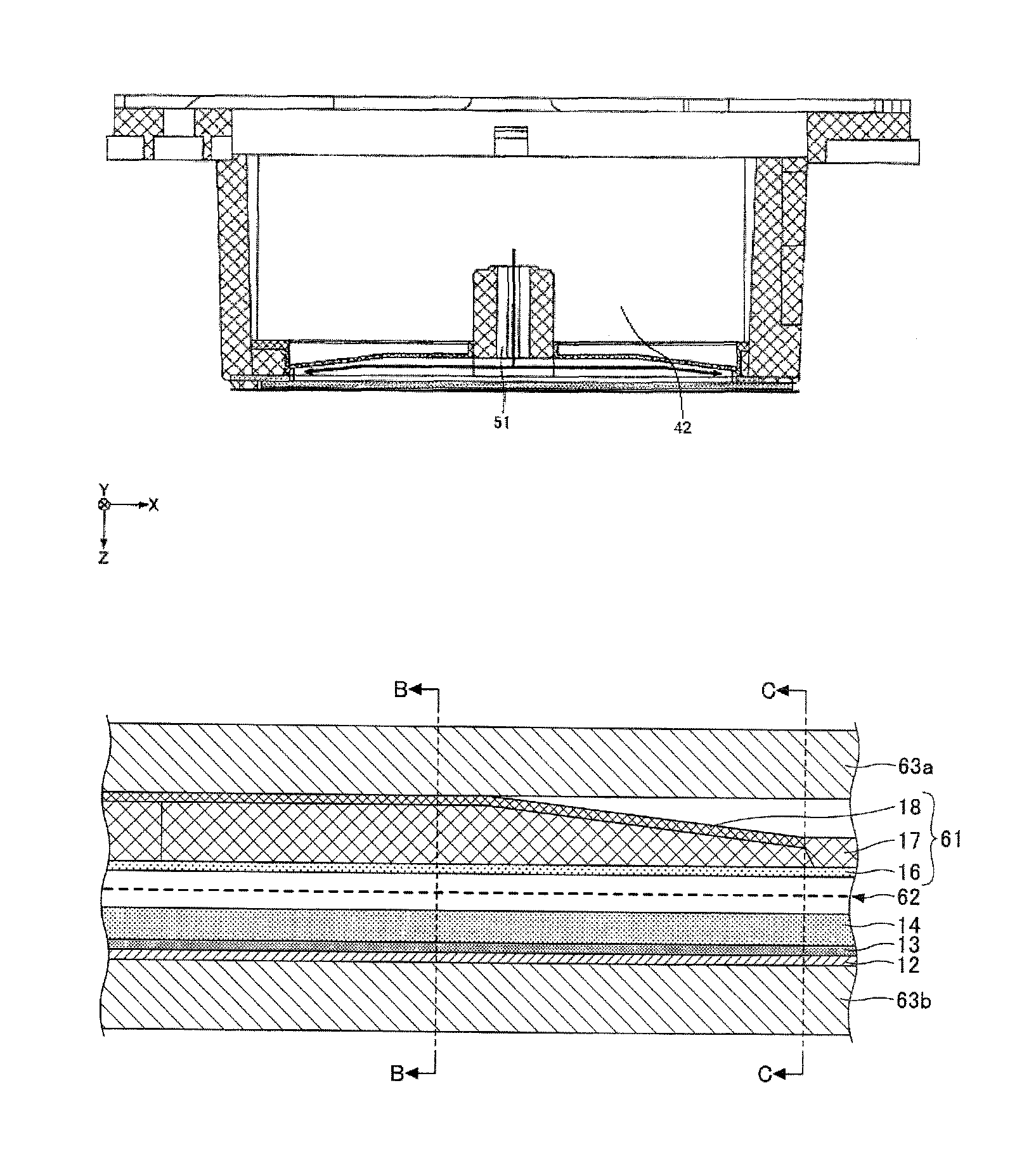
[0046]There is explained a configuration example of a droplet discharge head according to the embodiment of the present invention.

[0047]The droplet discharge head according to the embodiment includes a nozzle substrate in which a nozzle for discharging liquid droplets is formed; an individual liquid chamber substrate in which an individual liquid chamber is formed, wherein the individual liquid chamber is in communication with the nozzle; and a common liquid chamber substrate in which a common liquid chamber is formed, wherein the common liquid chamber is in communication with the individual liquid chamber. Here, the nozzle substrate, the individual liquid chamber substrate, and the common liquid chamber substrate are laminated. At least a portion of a top surface of the common liquid chamber has flexibility, and the top surface of the common liquid chamber is disposed at a side opposite to a side at which the nozzle substrate is disposed. The common liquid chamber has a shape such ...


PUM


Abstract

Disclosed is a droplet discharge head including a nozzle substrate including a nozzle, an individual liquid chamber substrate including an individual liquid chamber, and a common liquid chamber substrate including a common liquid chamber, wherein the substrates are laminated, wherein a portion of a top surface of the common liquid chamber is flexible, wherein the top surface of the common liquid chamber is disposed at a side opposite to another side at which the nozzle plate is disposed, wherein the common liquid chamber has a shape such that one portion of the common liquid chamber is narrowed in a direction in which the substrates are laminated, wherein a height of a wall of the common liquid chamber in the direction in which the substrates are laminated is constant, and wherein the wall is substantially perpendicular to the top surface.

Description

BACKGROUND OF THE INVENTION[0001]1. Field of the Invention[0002]The present invention relates to a droplet discharge head and an image forming apparatus.[0003]2. Description of the Related Art[0004]An inkjet recording apparatus including a liquid droplet discharge device has been known as an image forming apparatus. Here, in the liquid droplet discharge device, a droplet discharge head is used as a recording head. Examples of the image forming apparatus include a printer, a facsimile machine, a copier, and a combined machine thereof.[0005]The inkjet recording apparatus performs recording by discharging a recording liquid (ink) onto a paper sheet. Here, the sheet is not limited to the paper sheet. The sheet includes, for example, a transparency (an OHP sheet). The sheet means something to which a recording liquid, such as ink, or other liquids can be adhered. The sheet also referred to as a “medium to be recorded,” a “recording medium,” or a “recording paper.” The inkjet recording ap...

Claims


Application Information

Patent Timeline
Patent Type & Authority Patents(United States)
IPC IPC(8): B41J2/015B41J2/14B41J2/16
CPCB41J2/1433B41J2/14233B41J2/161B41J2/1623B41J2002/14362B41J2202/11
Inventor SASAKI, TAKAFUMITAJIMA, YUKITOSHI
Owner RICOH KK
Why Eureka
Try Eureka