Handheld medical devices including microwave amplifier unit at device handle

a technology of microwave amplifier and handle, which is applied in the field of hand-held medical devices, can solve the problems of affecting the surgeon's full freedom of movement, the cost of cable assemblies, and the interference of wireless networks deployed, so as to facilitate cleaning and/or serialization of the prob

a technology of microwave amplifier and handle, which is applied in the field of hand-held medical devices, can solve the problems of affecting the surgeon's full freedom of movement, the cost of cable assemblies, and the interference of wireless networks deployed, so as to facilitate cleaning and/or serialization of the prob

US9023025B2Active Publication Date: 2015-05-05TYCO HEALTHCARE GRP LP

Image

  • Handheld medical devices including microwave amplifier unit at device handle
  • Handheld medical devices including microwave amplifier unit at device handle
  • Handheld medical devices including microwave amplifier unit at device handle

Examples


Embodiment Construction

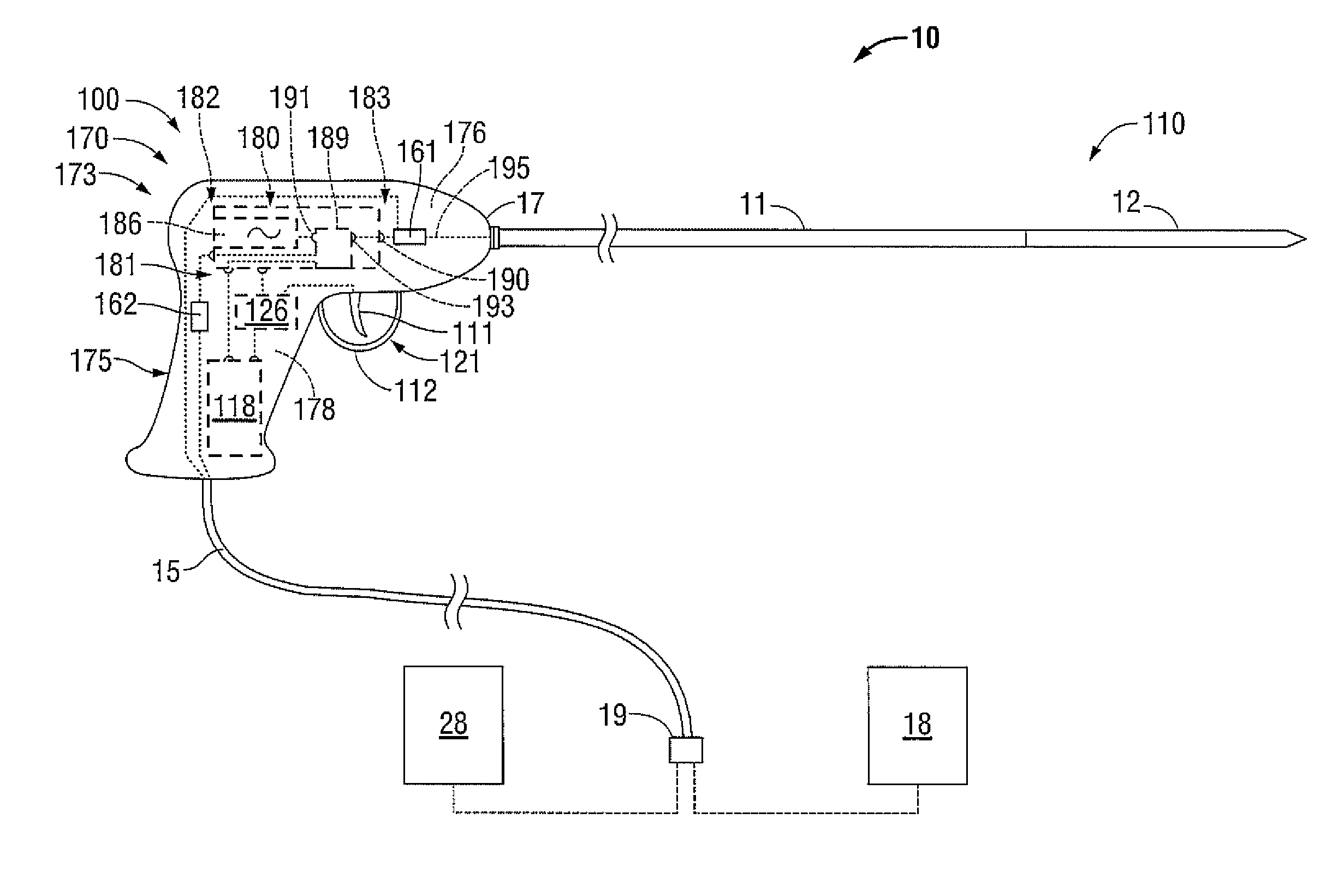
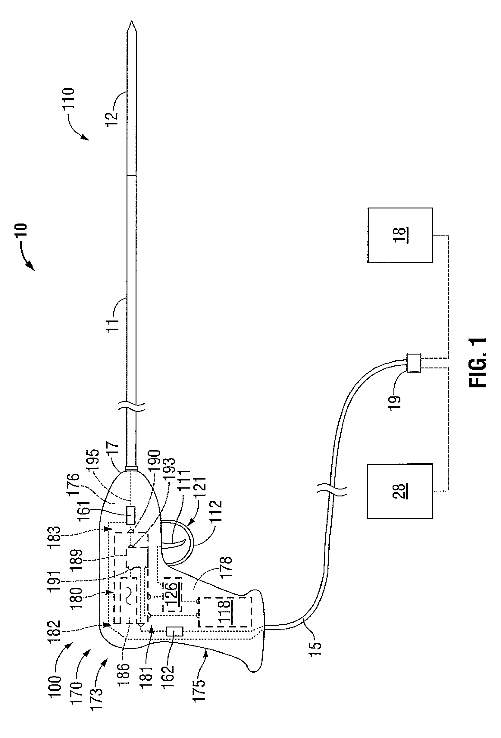
[0039]Hereinafter, embodiments of the presently-disclosed handheld medical device with a microwave amplifier unit at the device handle, electrosurgical systems including the same, methods of directing energy to tissue using the same, and methods of manufacturing the same will be described with reference to the accompanying drawings. Like reference numerals may refer to similar or identical elements throughout the description of the figures. As shown in the drawings and as used in this description, and as is traditional when referring to relative positioning on an object, the term “proximal” refers to that portion of the apparatus, or component thereof, closer to the user and the term “distal” refers to that portion of the apparatus, or component thereof, farther from the user. In the following description, well-known functions or constructions are not described in detail to avoid obscuring the present disclosure in unnecessary detail.

[0040]This description may use the phrases “in an...


PUM


Abstract

A medical device includes a handle assembly including a distal end, a probe extending distally from the distal end of the handle assembly, and a microwave amplifier unit disposed within the handle assembly. The microwave amplifier unit is adapted to amplify a high-frequency input signal to generate a high-frequency output signal to be transmitted to the probe.

Description

BACKGROUND[0001]1. Technical Field[0002]The present disclosure relates to handheld medical devices suitable for use in tissue ablation applications. More particularly, the present disclosure relates to medical devices with a microwave amplifier unit at the device handle, electrosurgical systems including the same, methods of directing energy to tissue using the same, and methods of manufacturing the same.[0003]2. Discussion of Related Art[0004]Electrosurgical instruments have become widely used by surgeons. Electrosurgery involves the application of thermal and / or electrical energy to cut, dissect, ablate, coagulate, cauterize, seal or otherwise treat biological tissue during a surgical procedure. Electrosurgery is typically performed using a handpiece including a surgical instrument (e.g., end effector or ablation probe) adapted to transmit energy to a tissue site during electrosurgical procedures, a remote electrosurgical generator operable to output energy, and a cable assembly o...

Claims


Application Information

Patent Timeline
05 May 2015
Publication
US9023025B2
IPC
A61B18/18; A61B18/00; A61B19/00
CPC
A61B18/1815; A61B2018/00922; A61B2018/1823; A61B2019/4836; A61B2090/0807
Inventors
BEHNKE, II, ROBERT J.; JENSEN, JEFFREY L.