
Crutch apparatus and method for designing and fabricating

a technology which is applied in the field of designing and fabricating of the forearm, can solve the problems of forearm discomfort and instability of the forearm moun

Active Publication Date: 2015-05-19
3D SYST INC
View PDF16 Cites 7 Cited by
  • Summary
  • Abstract
  • Description
  • Claims
  • Application Information

AI Technical Summary

Benefits of technology

[0004]A Lofstrand crutch includes a grip and a forearm support that are coupled to an elongated member that extends from the forearm support to the ground. The patient can place the forearm support around the forearm and grasp the grip. The grip and the forearm support can be coupled to a proximal portion of the elongated member and the distal end of the elongated member can be an elastic foot member that prevents the crutch from slipping when the foot is placed on the ground.
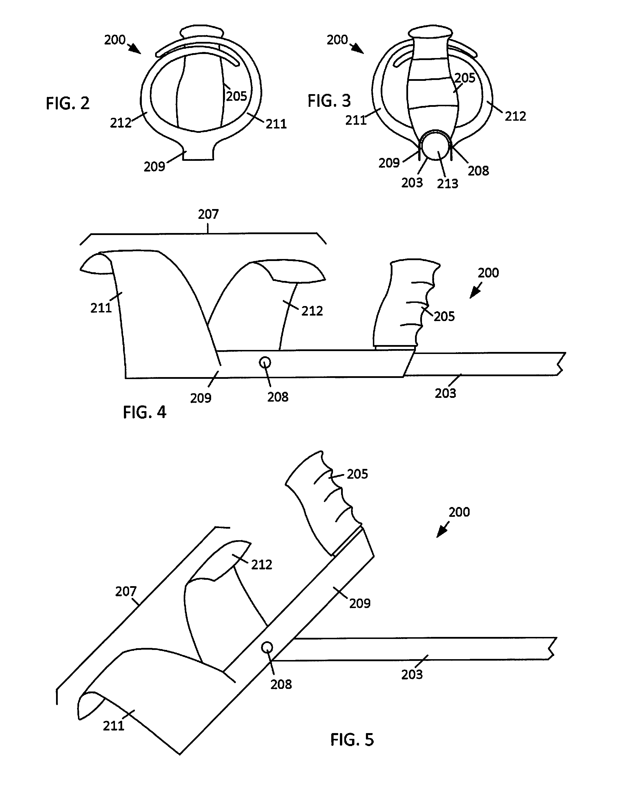
[0006]In an embodiment, the grip and forearm support can be a single unitary structure made of a homogeneous material that is rigidly coupled to the elongated member. In other embodiments, the grip and forearm support can be separate structures that are independently coupled to the elongated member. In yet another embodiment, the forearm support can be coupled to the elongated member with a hinge that can have one or more locked positions. In the first locked position, the locking mechanism can rigidly hold the forearm support in the normal use position or angle relative to the elongated member. In an unlocked position, the hinge can allow the elongated member to rotate relative to the forearm support. In a second locked position, the locking mechanism can rigidly hold the forearm support in the second use position or angle relative to the elongated member that is different than the normal use position.
[0011]In an embodiment, the forearm support has a smooth inner surface that conforms to the digital representation of the scanned surface of the limb and closely matches the surface measurements of the patient's body. Because the inner surface of the forearm support accurately conforms to the patient to provide a very close fit, the surface of the arm matches the inner surface of the forearm support. Thus, the forearm support can be used by the patient without any padding. The forearm support can be made of a hard plastic material that provides structural strength to support the forearm but can also be flexible to allow the forearm support to be elastically deformed to allow a user to place the forearm support on the forearm. In order to be comfortable, the inner surface of the hard plastic forearm support should also be very smooth. In an embodiment, the inner surface can have a surface finish of less than 500 Ra μinch. In an embodiment, the innermost surface of the structural layer of the forearm support can be made of a homogeneous plastic material. In other embodiments, the entire forearm support can be made of a homogeneous plastic material. A forearm support that can be worn by a patient without inner surface padding has several benefits including: simplified forearm support design and construction, less material for fabrication, lower weight, lower profile thickness, better ventilation, no absorption of water, easier cleaning, etc.

Problems solved by technology

Because the forearm support is generic, forearm discomfort and instability of the forearm mounts is a frequent complaint of the devices.

Method used


Image

  • Crutch apparatus and method for designing and fabricating
  • Crutch apparatus and method for designing and fabricating
  • Crutch apparatus and method for designing and fabricating

Examples


Embodiment Construction

[0029]The present invention is directed towards Lofstrand devices in which a hand grip and forearm mounts that each include surfaces that contact the patient's body. The patient contact areas of the hand grip and forearm mounts are designed and fabricated to conform to the patient's forearm and wrist anatomy and morphology. Lofstrand crutches are designed to load the forearm rather than traditional crutches that load the palm. Because the present invention is directed towards a patient specific crutch design, the forearm support of the crutch can be design to conform to the forearm of the patient and avoid boney prominences on the patient.

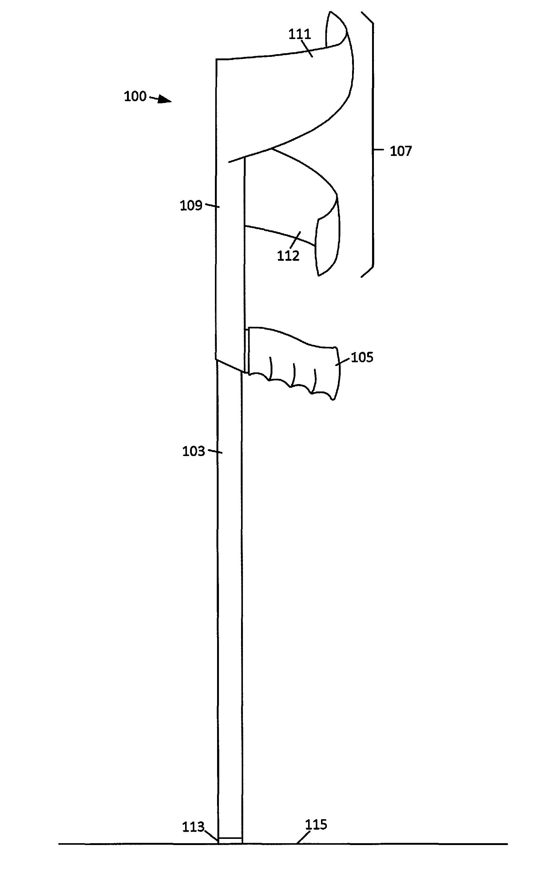
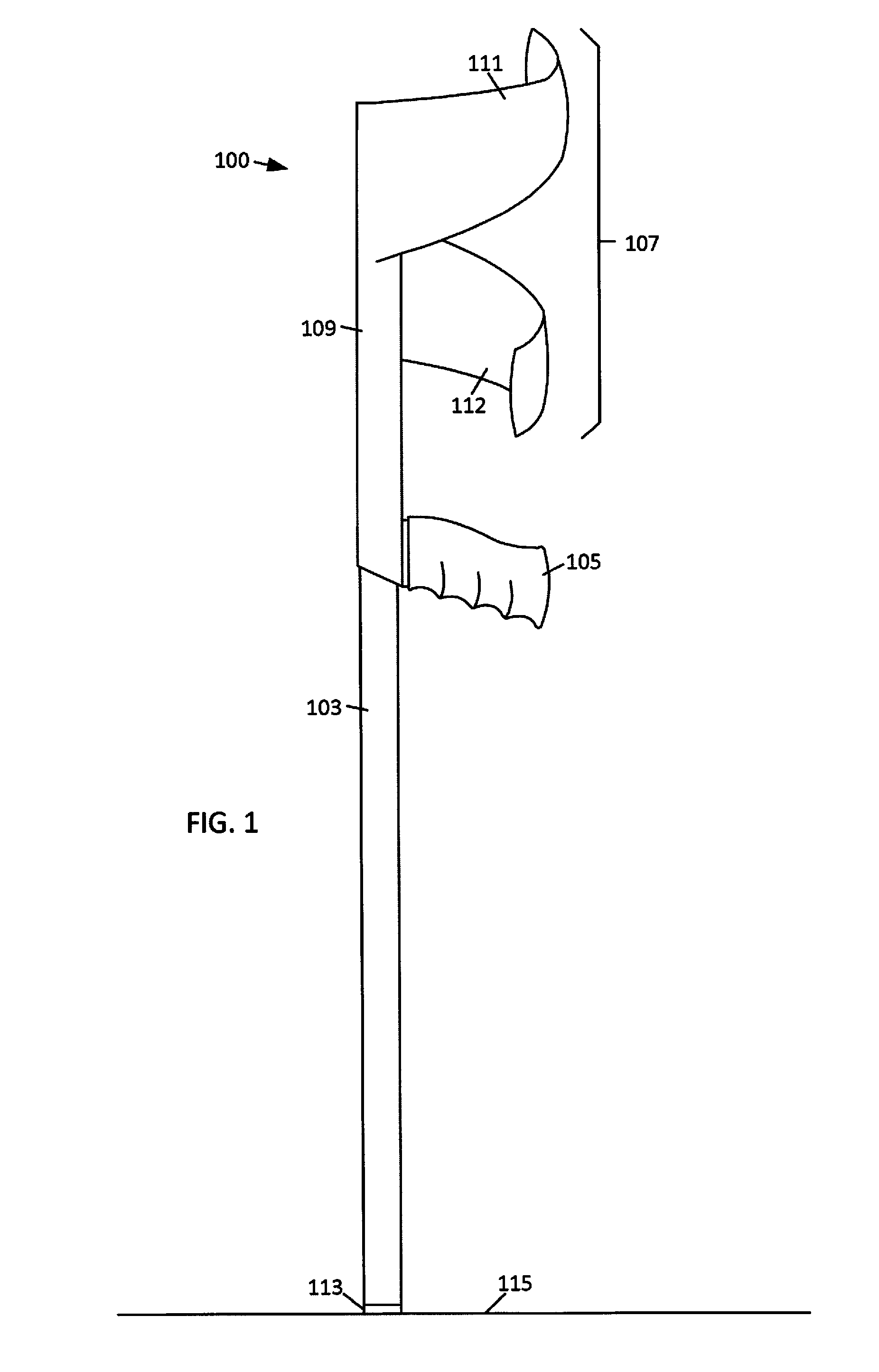
[0030]With reference to FIG. 1, an embodiment of a Lofstrand crutch 100 is illustrated. The illustrated Lofstrand crutch 100 includes an elongated member 103, a hand grip 105 and a forearm support 107. A non-slip foot 113 can be coupled to the distal end of the elongated member 103 which can prevent the crutch 101 from sliding when the foot 113 is ...


PUM


Abstract

A crutch includes a grip and a forearm support that are coupled to an elongated member that extends from the forearm support to the ground. The inner surface of the forearm support can correspond to a digital representation of a forearm of the patient and the outer surface of the hand grip can correspond to a digital representation of a palmar surface of the patient's hand in at least a partially closed position.

Description

CROSS-REFERENCE TO RELATED APPLICATIONS[0001]This application claims priority to U.S. Provisional Patent Application No. 61 / 785,903, “Spiral Brace And Method For Automated Spiral Brace Design” filed Mar. 14, 2013, U.S. Provisional Patent Application No. 61 / 615,139, “Unloading Structural Supports” filed Mar. 23, 2012 and U.S. Provisional Patent Application No. 61 / 720,861, “Spiral Brace” filed Oct. 31, 2012 and is a continuation-in-part of PCT Patent Application No. PCT / US2012 / 051612, “Adjustable Brace” filed Aug. 20, 2012 which claims priority to U.S. patent application Ser. No. 13 / 214,096, “Adjustable Brace” filed Aug. 19, 2011 which is a continuation-in-part of U.S. patent application Ser. No. 12 / 820,968, “Modular Custom Braces, Casts And Devices And Methods For Designing And Fabricating” filed Jun. 22, 2010 which is a continuation-in-part of U.S. patent application Ser. No. 12 / 615,196, now U.S. Pat. No. 8,005,651, “Custom Braces, Casts and Devices And Methods For Designing And Fab...

Claims


Application Information

Patent Timeline
Patent Type & Authority Patents(United States)
IPC IPC(8): A61H3/02A61B5/00A61H3/00A61H3/04A61N1/40A63B21/00A63B59/00G08B21/04H04M1/724H04M1/72418
CPCA61H3/02A61B5/0064H04M1/72519A61H2003/006A61H2201/0184A61H2201/5094A61H3/04A63B21/1469A63B21/1476A63B59/0025G08B21/0446A61H2201/0161A61H2201/10A61H2201/1647A61H2201/5071A61H2201/5084A61H2201/5097A61H2230/60A61N1/40H04M1/72536H04M2250/12A63B21/4035A63B60/12A63B60/10A63B60/08A63B21/4039B33Y80/00H04M1/72418H04M1/724
Inventor SUMMIT, SCOTTTRAUNER, KENNETH B
Owner 3D SYST INC
Learn More