Energy converting device having an eccentric rotor

a technology of energy conversion device and eccentric rotor, which is applied in the direction of dynamo-electric machines, magnetic circuit rotating parts, magnetic circuit shape/form/construction, etc., can solve the problems of inability to use 2-deimentional magnetic analysis tools, complicated analysis of air-gap flux distribution, and still-traditional axial-flux motors. , to achieve the effect of smoother generated torque, simple rotor structure and evenly distributed

Active Publication Date: 2015-05-19
NATIONAL YUNLIN UNIVERSITY OF SCIENCE AND TECHNOLOGY
View PDF7 Cites 0 Cited by
  • Summary
  • Abstract
  • Description
  • Claims
  • Application Information

AI Technical Summary

Benefits of technology

[0011]The object of the present invention is to provide an energy converting device having an eccentric rotor. Particularly, it relates to an energy converting device having an eccentric rotor for converting electric energy into mechanical energy. Its advantages and functions are listed as follows. The rotor structure is simple and its magnetic field is evenly distributed. The magnetic flux variation is close to a sine wave. The generated torque is smoother. It can improve the motor's acceleration and deceleration performance. In addition, it can be seamlessly combined with the cycloidal speed reducer so as to form a cycloidal motor.

Problems solved by technology

However, the traditional axial-flux motor still has the following drawbacks and problems.
[2] Analysis of the air-gap flux distribution is complicated.
It is inappropriate to use 2-deimentional magnetic analysis tool to analyze its flux distribution.
Three-dimensional analysis is required, making its design more costly
The combined volume of the motor (snot shown) and the cycloidal speed reducer may be too large for many applications.

Method used


Image

  • Energy converting device having an eccentric rotor
  • Energy converting device having an eccentric rotor
  • Energy converting device having an eccentric rotor

Examples


Embodiment Construction

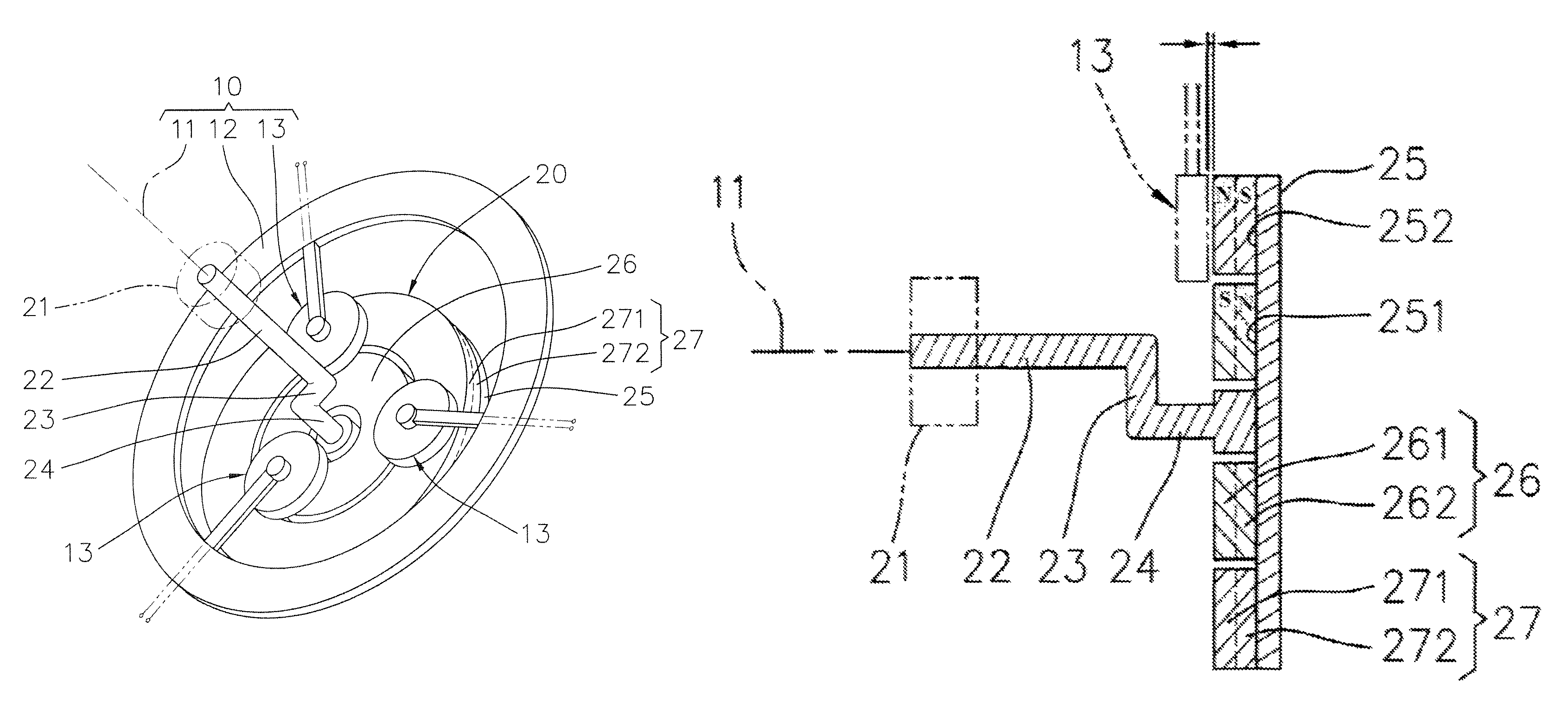
[0046]The present invention relates to an energy converting device having an eccentric rotor. It has two converting methods. One is to be used as an electric generator. The other one is to be used as a motor.

[0047]Referring to FIGS. 5 to 10, it is the first preferred embodiment of this invention which is to be used as an electric generator. This invention is an energy converting device having an eccentric rotor. It mainly comprises a fixed portion 10 and an eccentric rotor 20.

[0048]With regard to this fixed portion 10, it has a central axis 11, an outer frame 12, and a plurality of fixed coil portions 13. In this case, there are three fixed coil portions 13 (at least two; preferably three or four or multiple thereof). The fixed coil portions 10 are equally spaced from the central axis 11 (if there are only two fixed coil portions 10, they should be separated by 90 degrees). The fixed coil portions 13 are secured on the outer frame 12 and are separated. Each fixed coil portion 13 has...


PUM


Abstract

An energy converting device having an eccentric rotor includes a fixed portion and an eccentric rotor. This fixed portion has a central axis, an outer frame, and several fixed coil portions. The eccentric rotor has a bearing, a rotatory shaft, an eccentric arm, an eccentric shaft portion, a supporting plate, an inner annular magnetic portion, and an outer annular magnetic portion. The inner magnetic portion and the outer magnetic portion are concentric and aligned with the eccentric shaft portion. The eccentric shaft portion is offset from the rotary shaft. When the rotary shaft of the eccentric rotor rotates, these fixed coil portions cut through the inner magnetic portion and the outer magnetic portion repeatedly, so magnetic flux passing through the coils alternates accordingly to generate electromotive force. Conversely, it can be used as an electric motor. In addition, it can be integrated with a cycloidal speed reducer to form a motor with speed reduction and torque augmentation capability. The integrated cycloidal motor is compact, does not need a shaft coupler to transmit power from a motor to the reducer, and therefore may operate more smoothly.

Description

BACKGROUND OF THE INVENTION[0001]1. Field of the Invention[0002]The present invention relates to an energy converting device having an eccentric rotor. Particularly, it relates to an energy converting device having an eccentric rotor for converting electric energy into mechanical energy. Its advantages and functions are listed as follows. The rotor structure is simple and its magnetic field is evenly distributed. The magnetic flux variation is close to a sine wave. The generated torque is smoother. It can improve the motor's acceleration and deceleration performance. In addition, it can be seamlessly combined with a cycloidal speed reducer so as to form a cycloidal motor.[0003]2. Description of the Prior Art[0004]The traditional motor can be classified into the radial-flux motor 90 and the axial-flux motor 80 by the flux direction. Most motors belong to the radial-flux motor 90 as illustrated in FIG. 1. Its simplified operation principle can be seen in FIG. 2.[0005]FIG. 3A is a cros...

Claims


Application Information

Patent Timeline
Patent Type & Authority Patents(United States)
IPC IPC(8): H02K21/12H02K21/24H02K7/075
CPCH02K7/075H02K21/24
Inventor WU, SHANG-TEH
Owner NATIONAL YUNLIN UNIVERSITY OF SCIENCE AND TECHNOLOGY
Why Eureka
Try Eureka