Identification devices

a technology of identification devices and identification signals, applied in the direction of visible signalling systems, instruments, signalling systems, etc., can solve the problems of reducing the efficiency of staff and some common resources such as surgical theatres and emergency departments, and achieve the effects of strong activation signals, low power consumption, and extended battery li

Inactive Publication Date: 2015-05-26
SONITOR TECH
View PDF23 Cites 14 Cited by
  • Summary
  • Abstract
  • Description
  • Claims
  • Application Information

AI Technical Summary

Benefits of technology

[0009]Thus it will be seen by those skilled in the art that in accordance with the invention an active ultrasound transmitter, which will typically be of relatively high value, can be accommodated in an outer housing which can protect it from contamination by dirt, fluid and infection agents whilst still allowing ultrasound signals to pass from the transmitter. If contamination of the main transmitter unit can be prevented, it is then easy for it to be re-used without requiring sterilization which would be difficult to achieve in view of the sensitive electronics and transducers associated with it. The outer housing could be cleaned and sterilized between each use (as it does not contain the sensitive electronics), but preferably it is disposable. It can be seen therefore that the benefits afforded by an ultrasonic identification and tracking system can be enjoyed whilst minimizing the cost thereof allowing reuse of the transmitter units by utilizing a relatively inexpensive disposable part which obviates the need for cleaning / sterilization and minimizes the risk of cross infection.
[0014]The outer housing is preferably configured so that the transmitter unit can be sealed into it before attachment to a patient or patient's strap. This minimizes the risk of contamination entering the interior of the housing. The housing is preferably closed by a single-use catch which, once broken to allow release, cannot be re-used. Such an arrangement makes the device difficult to remove without special tools and also prevents inadvertent or deliberate re-use of potentially contaminated outer housings.
[0016]The power source to the transmitter unit could be provided internally within the transmitter unit or, conceivably, externally of the whole device. However, the applicant has appreciated that in a particularly beneficial set of embodiments, a battery is provided within the outer housing such that it can be connected to the transmitter unit when the latter is inserted in the housing. This is beneficial since it means that the battery can be discarded along with the outer housing when each patient has finished using the device, thus ensuring that a fresh battery is available for each new patient. It also means that the transmitter unit itself does not need its own, longer life battery which saves on costs.
[0023]The activating signal could be any chosen signal although in accordance with preferred embodiments the signal is at a significantly higher power than other signals received by the device or signals transmitted by the device. This is easily achievable since such a signal will only be required relatively infrequently and can be transmitted from a transmitter placed in very close proximity to the identification device. The device might, for example, be placed in a docking station or a handheld transmitter could be placed next to or on top of the device. Another advantage of utilizing a very strong activation signal is that the requirement for amplification and / or processing of the signal is reduced which reduces the power requirement for the sleep state.

Problems solved by technology

There is a separate problem in many hospitals that the efficiency of staff and some common resources such as surgical theatres and emergency departments can be reduced if patients cannot be located at the appropriate time thus requiring staff to go looking for them and holding up other patients awaiting attention or therapy, or otherwise impeding an optimal workflow.

Method used


Image

  • Identification devices
  • Identification devices
  • Identification devices

Examples


Embodiment Construction

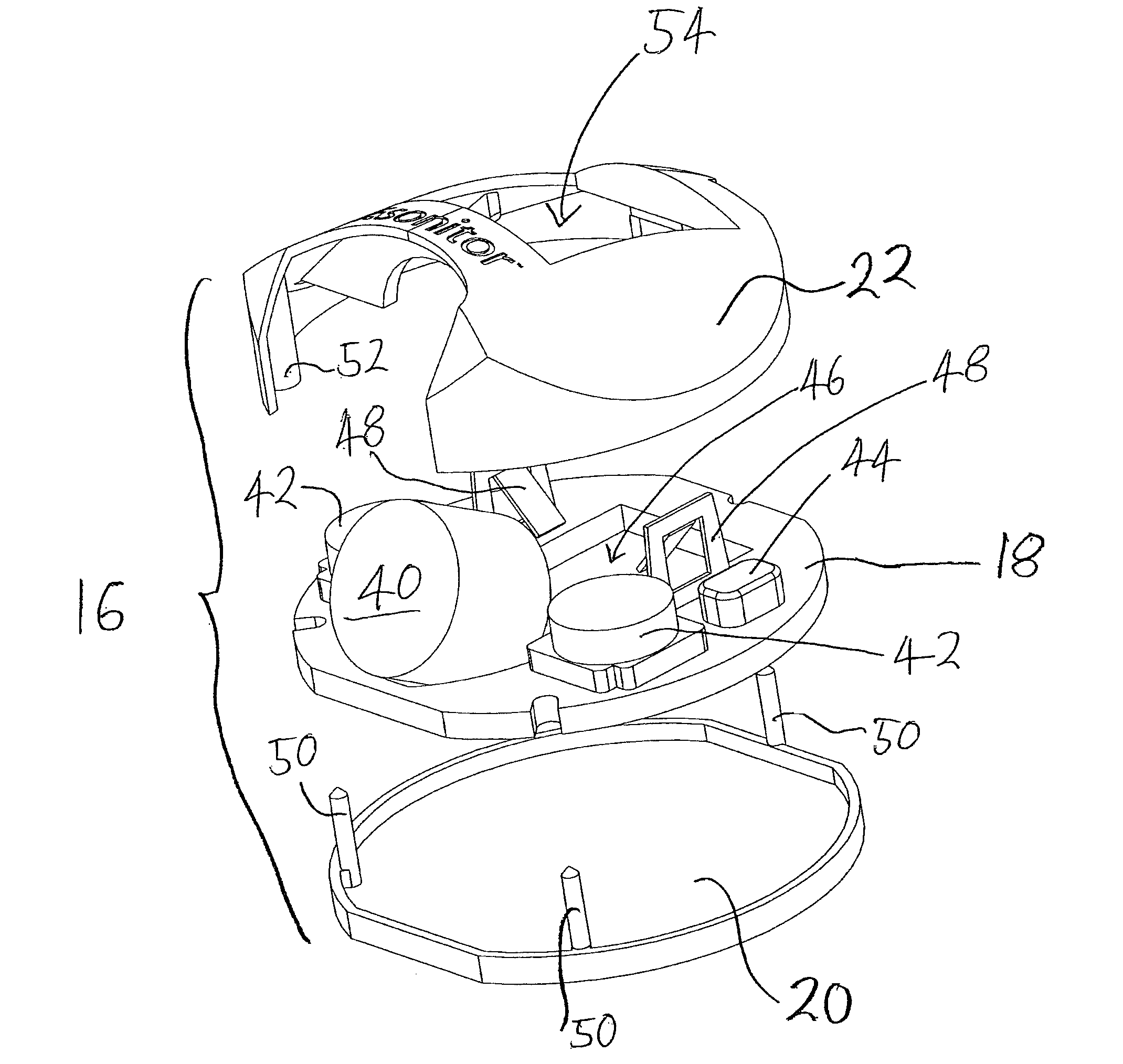
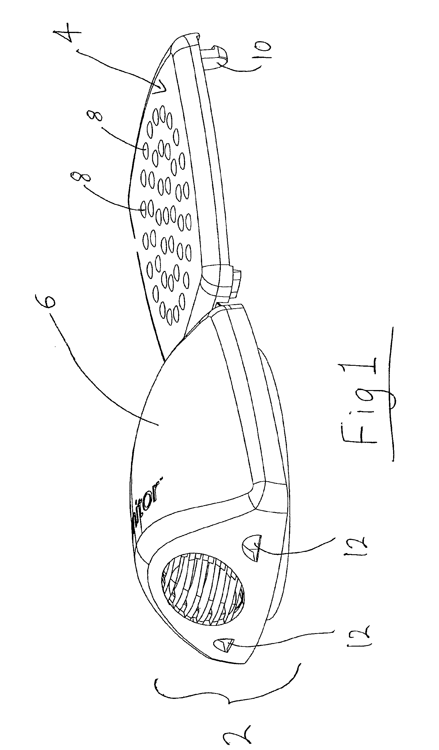
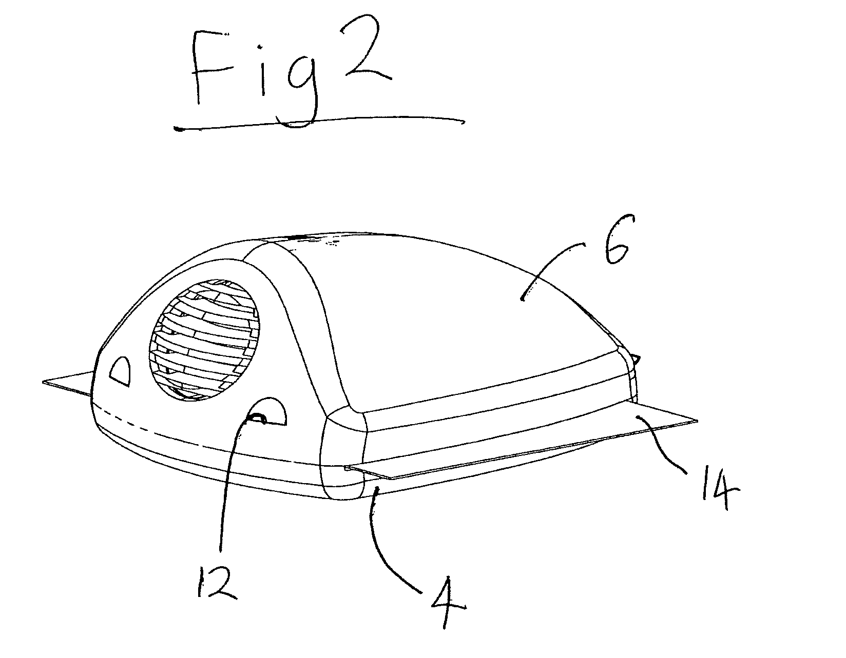
[0032]FIG. 1 shows an ultrasonic identification tag for identifying, and / or tracking the movements of, a patient in a hospital. The embodiment described herein has been developed so as to be particularly suitable for this application, although the skilled person will appreciate that the principles embodied may find useful application in a wide variety of uses.

[0033]The tag comprises two main parts which are a main body portion 2 and a hinged flap portion 4. The flap portion 4 is molded integrally with the upper body shell 6 to faun a so-called living hinge (not shown). On the upper face (as seen in FIG. 1) of the flap portion 4 are formed a series of rounded protrusions 8. This will be the part of the tag which presses against the patient's skin, and the protrusions 8 help to prevent the tag from slipping and make the tag more comfortable for the patient to wear for a prolonged period of time without causing skin irritations or reactions. The material of the outer shell is biodegrad...


PUM


Abstract

An identification device comprising an ultrasound transmitter unit (16) and an outer housing (6) which receives said transmitter unit (16), said outer housing (6) comprising one or more apertures (32) which are sealed by a membrane, said membrane being substantially transparent to ultrasound when compared to the rest of the housing.

Description

[0001]This application is entitled to the benefit of, and incorporates by reference essential subject matter disclosed in PCT Application No. PCT / GB2008 / 003658 filed on Oct. 28, 2008, which claims priority to Great Britain Patent Application No. 0721162.6 filed Oct. 29, 2007.BACKGROUND OF THE INVENTION[0002]1. Technical Field[0003]This invention relates to identification devices which can be fitted to a person, animal or object to permit identification and / or real-time location tracking of the same.[0004]2. Background Information[0005]There is an important need in hospitals to be able to positively identify patients of the hospital to ensure that confidentiality is maintained and that the correct treatment is given. Conventionally this is achieved using single-use wrist bands on which identifying text, or occasionally a bar code, may be written or printed.[0006]There is a separate problem in many hospitals that the efficiency of staff and some common resources such as surgical theat...

Claims


Application Information

Patent Timeline
Patent Type & Authority Patents(United States)
IPC IPC(8): G08B1/08G09F3/00
CPCG09F3/005
Inventor BOOIJ, WILFRED EDWINOYEN, ARNE
Owner SONITOR TECH
Why Eureka
Try Eureka