Powered prosthetic hip joint

a hip joint and hip joint technology, applied in the field of prosthetic hip joints, can solve the problems of limited number of products available, affecting the mobility of users, and the stance control of hydraulic augmented mechanical hip joints that does not allow for stable hip positioning while standing, so as to reduce the and increase the apparent and/or effective stiffness of the hip joint

Active Publication Date: 2015-06-02
OSSUR HF
View PDF127 Cites 36 Cited by
  • Summary
  • Abstract
  • Description
  • Claims
  • Application Information

AI Technical Summary

Benefits of technology

[0013]Some embodiments include a linear actuator and a rotary actuator, which are used to rotate a prosthetic hip joint. In several embodiments, a rotary actuator is primarily used to rotate a hip joint while a linear actuator is used to change the rotational plane of the rotary actuator. This configuration helps simulate the degrees of freedom provided by a natural hip due to the head of a natural femur and the socket of a natural hip.
[0014]In accordance with another embodiment, a powered prosthetic hip joint is provided allowing for a flexible connection of the upper thigh segment to the socket, such that frontal plane rotation is achieved for improved user comfort and fulfillment of the natural abduction-adduction motion of the non-pathological hip joint. Relative rotation of the hip prosthetic proximal end with respect to the socket system in the frontal plane is achieved using a compliant mechanical structure, which deflects when load is transferred to the ground from the socket, such as observed during stance phase of walking or when shifting weight from one lower-limb to the other while standing. The compliant mechanical structure can be a compliant component, compliant linkage, and / or a compliant connector.
[0015]In accordance with another embodiment, a dual joint prosthetic device is provided allowing the device to replace lost function at the hip and knee levels. This embodiment allows synchronized operation of both joints through the use of a two-degree of freedom central controller and can improve the device's capacity to restore natural gait for locomotion activities most often encountered in daily living. Several embodiments of dual joint prosthetic devices use a powered proximal joint (i.e., hip joint), coupled with either a second powered joint on the distal end (i.e., knee joint) or a passive stance controllable device.
[0017]In accordance with another embodiment, a method of operating a powered prosthetic hip joint is provided. The method can comprise sensing if the prosthetic foot is in contact with a ground surface or not in contact with the ground surface. The method can also comprise operating an actuator of the powered prosthetic hip joint to provide resistance to movement between the components of the hip joint, thereby increasing a stiffness of the hip joint if the prosthetic foot is in contact with the ground surface. The method can also comprise operating the actuator of the powered prosthetic hip joint to decrease a stiffness of the hip joint if the prosthetic foot is not in contact with the ground surface.
[0018]In accordance with another embodiment, a method of operating a powered prosthetic hip joint is provided. The method can comprise sensing if the prosthetic foot is in contact with a ground surface or not in contact with the ground surface. The method can also comprise operating an actuator of the powered prosthetic hip joint to provide resistance to movement between the components of the hip joint, thereby increasing an apparent and / or effective stiffness of the hip joint if the prosthetic foot is in contact with the ground surface. The method can also comprise operating the actuator of the powered prosthetic hip joint to decrease an apparent and / or effective stiffness of the hip joint if the prosthetic foot is not in contact with the ground surface. In this application, apparent stiffness is the rotational stiffness perceived by a typical, average user of the prosthetic hip. For example, a prosthetic hip with a higher apparent stiffness will typically feel less prone to hip rotation than a hip with lower apparent stiffness. In this application, effective stiffness includes all factors that influence the force required to rotate a joint. For example, damping characteristics and inertia influence effective stiffness.
[0035]In several embodiments, a method for operating a powered prosthetic hip joint operatively coupled to a prosthetic foot comprises determining if the prosthetic foot is in contact with a ground surface and operating an actuator of the powered prosthetic hip joint to increase a stiffness of the hip joint if the prosthetic foot is in contact with the ground surface. The method can also comprise operating the actuator of the powered prosthetic hip joint to decrease the stiffness of the hip joint if the prosthetic foot is not in contact with the ground surface.

Problems solved by technology

A very limited number of products are available to address this type of amputation by providing some basic function allowing the amputee to stand and walk.
However, lack of swing phase motion has been observed to greatly affect the mobility of the user.
However, the stance control employed by hydraulic augmented mechanical hip joints does not allow for stable hip positioning while standing.
This results in the user standing in the maximally extended hip position, which has been observed to affect the user's postural stability and cause significant gait deviation when transitioning from static standing to an ambulatory task (e.g., walking).
For example, damping characteristics and inertia influence effective stiffness.

Method used


Image

  • Powered prosthetic hip joint
  • Powered prosthetic hip joint
  • Powered prosthetic hip joint

Examples


Embodiment Construction

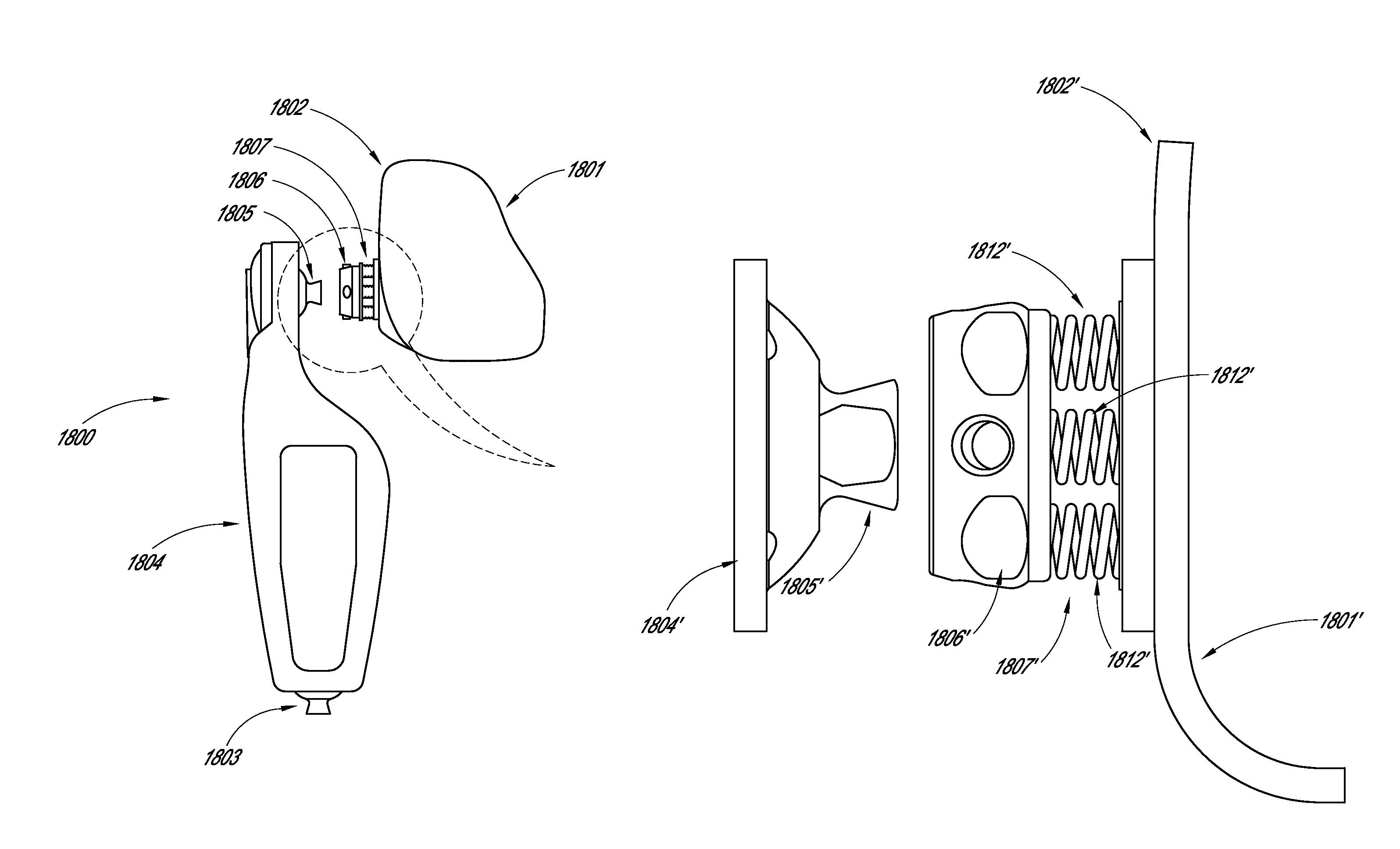
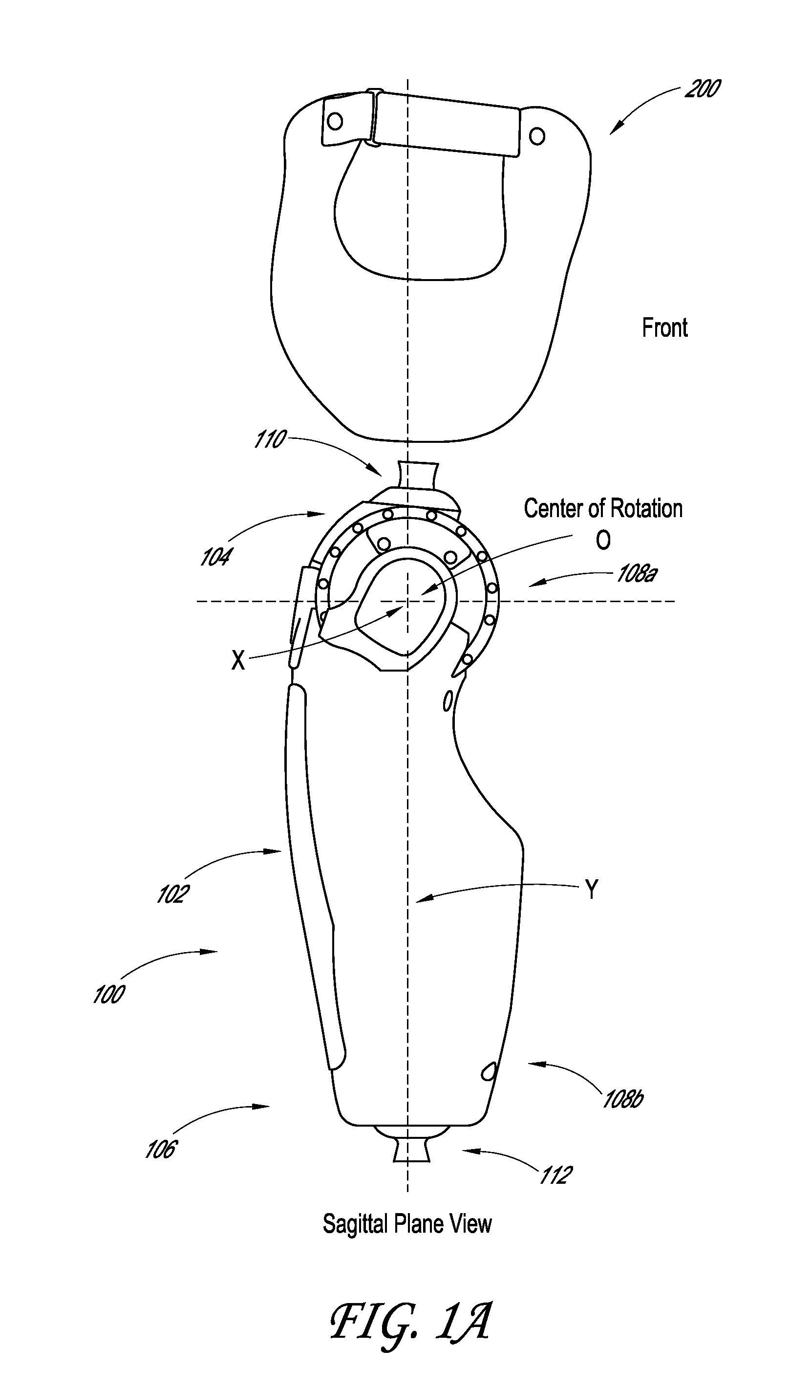
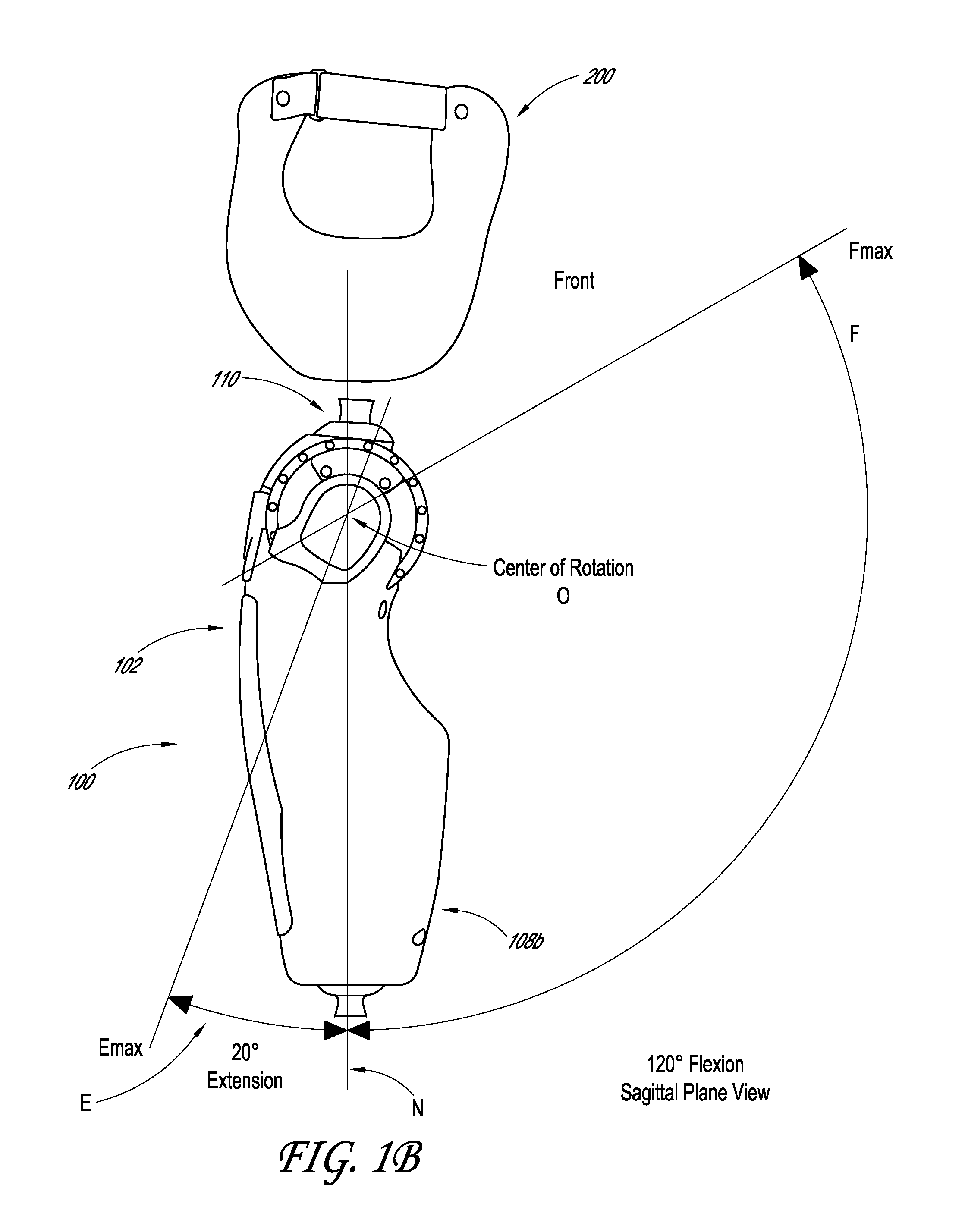
[0066]FIGS. 1a and 1b show one embodiment of a powered hip joint 100 of a prosthetic hip joint system. The powered hip joint 100 can have an elongated body 102 that extends between a proximal end 104 and a distal end 106, and can have a first connector 110 at the proximal end 104 and a second connector 112 at the distal end 106. In the illustrated embodiment, the first connector 110 can be a male pyramid connector and connect to a corresponding connector in distal end of a prosthetic component, such as a distal end of a prosthetic socket 200.

[0067]In some embodiments, the socket 200 is an envelope type socket that fits over a portion of an amputee's body, such as a pelvic area. Several embodiments include a socket that fits over a short stump, including a stump in the hip area. The socket 200 can have a connector to couple the socket 200 to the powered hip joint 100.

[0068]Several embodiments do not require a connector between the socket 200 and the powered hip joint 100. The socket ...


PUM


Abstract

A powered prosthetic thigh can have a proximal portion configured to couple to a prosthetic hip socket and can have a distal portion attached to the proximal portion. The distal portion can have a distal connector configured to couple to a prosthetic knee. The powered prosthetic thigh can also have a computer controlled actuator configured to rotate the prosthetic thigh relative to the prosthetic hip socket.

Description

CROSS-REFERENCE TO RELATED APPLICATION[0001]This application claims the benefit of U.S. Provisional Patent Application No. 61 / 617,540, entitled POWERED PROSTHETIC HIP JOINT, and filed Mar. 29, 2012, the entire contents of which are incorporated herein by reference.BACKGROUND[0002]1. Field[0003]Certain embodiments of the present invention are directed to a prosthetic hip joint, and more particularly to a microprocessor controlled prosthetic hip joint.[0004]2. Description of the Related Art[0005]The occurrence of hip-disarticulation amputations is increasing due to, among other reasons, various armed conflicts. A very limited number of products are available to address this type of amputation by providing some basic function allowing the amputee to stand and walk. Of the products that are currently available, they mainly consist of two types: passive mechanical linkages and hydraulic augmented mechanical linkages.[0006]Passive mechanical linkage hip joints are designed to provide basi...

Claims


Application Information

Patent Timeline
Patent Type & Authority Patents(United States)
IPC IPC(8): A61F2/48A61F2/74A61F2/60A61F2/64A61F2/66A61F2/68A61F2/70A61F2/76
CPCA61F2/60A61F2/605A61F2/68A61F2/64A61F2/66A61F2002/6836A61F2002/701A61F2002/705A61F2002/7625A61F2002/7635A61F2002/7645A61F2/70A61F2/80A61F2002/5018
Inventor LANGLOIS, DAVIDCLAUSEN, ARINBJORN VIGGOEINARSSON, RNI
Owner OSSUR HF
Why Eureka
Try Eureka