Liquid jetting apparatus

a technology of liquid jetting apparatus and nozzle, which is applied in the direction of printing apparatus, inking apparatus, other printing apparatus, etc., can solve the problems of difficult to accurately find the adjustment amount of the jet timing, inability and risk of failing to accurately correct the landing position. accurately, accurately correct the landing position, and accurately apprehend the displacement of each nozzl

Active Publication Date: 2015-06-02
BROTHER KOGYO KK
View PDF11 Cites 0 Cited by
  • Summary
  • Abstract
  • Description
  • Claims
  • Application Information

AI Technical Summary

Benefits of technology

[0008]Accordingly, an object of the present invention is to provide a liquid jetting apparatus capable of correctly apprehending the amount of displacement of nozzles when the head unit has expanded or contracted due to temperature change, and thereby accurately correcting the position of landing a liquid jetted from the nozzles onto a jet object.
[0015]According to the aspect of the present invention, when the head unit is expanding or contracting due to temperature change, because no displacement in the orthogonal direction occurs in the reference portion of the head unit restricted by the restriction mechanism, each portion of the head unit is displaced by the amount according to the temperature of the head unit and the distance from the reference portion. Therefore, it is possible to correctly apprehend the amount of displacement of each nozzle when the head unit has expanded or contracted due to temperature change. As a result, it is possible to accurately correct the landing position in the orthogonal direction perpendicular to the nozzle array direction. Further, if the restriction mechanism restricts the head unit by sandwiching the end portions thereof, then the reference portion corresponds to the portion of the head unit between the portions in contact with the restriction mechanism.
[0016]Further, the portion of the head unit inside of the outmost nozzle arrays in the orthogonal direction perpendicular to the nozzle array direction fits into the reference portion with no displacement in the orthogonal direction due to expansion and contraction of the head unit. Therefore, the distance between the reference position and the farthest nozzle becomes closer than in the case of providing the reference portion outside of the outmost nozzle columns. Therefore, when the head unit has expanded or contracted, the displacement of the nozzles away from the reference position becomes smaller and, as will be described hereinafter, it is sufficient for the landing position correction mechanism to apply a small correction amount to the landing position. By virtue of this, it is possible to accurately correct the landing position.

Problems solved by technology

According to a knowledge of the present inventors, if, by assumption, the nozzles deviate in the nozzle array direction between the plurality of heads, then even though the jet timing of the inks from the nozzles is corrected, etc., it is not possible to correct the landing position.
Nevertheless, it is difficult to accurately find the adjustment amount of the jet timing when the base plate expands for each head unit.
Hence, there is a risk of failing to accurately correct the landing position.

Method used


Image

  • Liquid jetting apparatus
  • Liquid jetting apparatus
  • Liquid jetting apparatus

Examples


Embodiment Construction

[0029]Hereinbelow, a preferred embodiment of the present teaching will be explained.

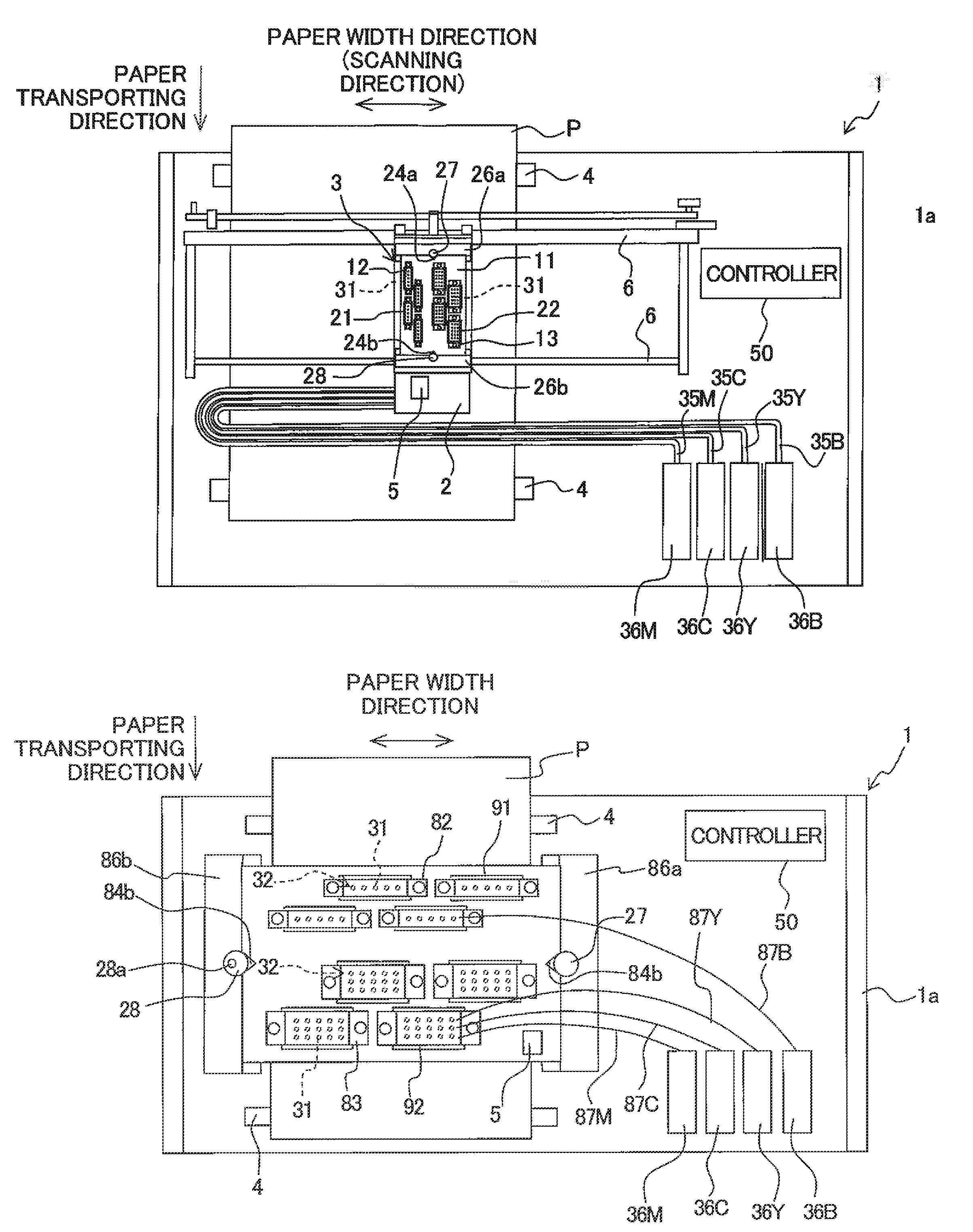
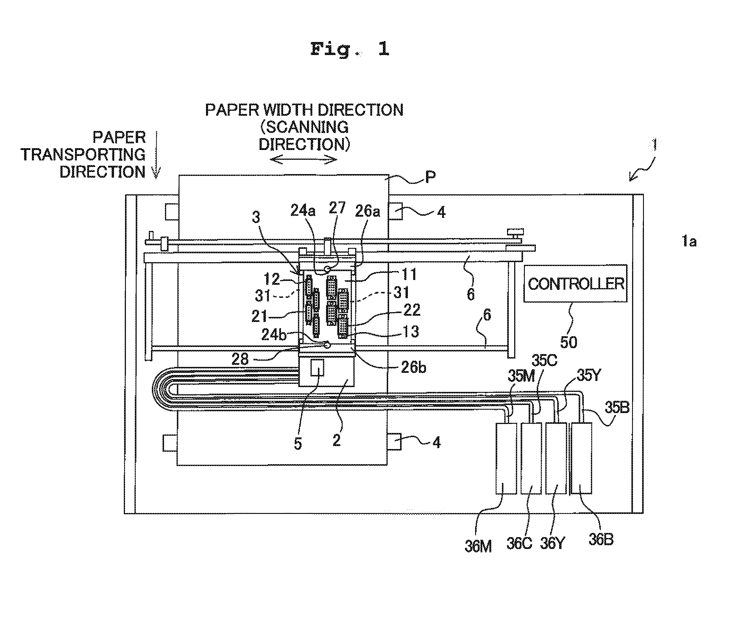
[0030]As shown in FIG. 1, as a liquid jetting apparatus in accordance with the present embodiment, a printer 1 includes a carriage 2, a head unit 3, paper transporting rollers 4, a temperature sensor 5, and the like. Further, operations of the printer 1 are controlled by a controller 50.

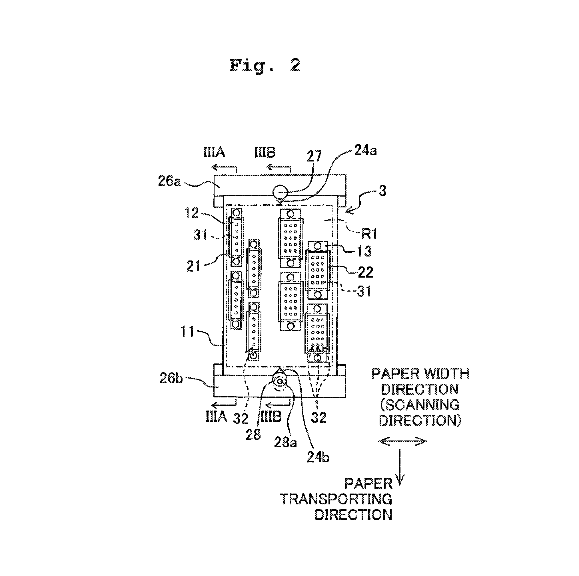
[0031]The carriage 2 reciprocates along two guide rails 6 extending in a scanning direction parallel to a paper width direction. The head unit 3 is installed on the carriage 2 to jet inks from a plurality of nozzles 31 formed in its lower surface. The paper transporting rollers 4 transport a recording paper P in a paper feeding direction perpendicular to the scanning direction. The temperature sensor 5 is provided on the carriage 2 to detect the temperature of the head unit 3. In particular, the temperature sensor 5 detects the temperature of an aftermentioned head holding plate 11. Alternatively, it may as well detec...


PUM


Abstract

A liquid jetting apparatus includes: a head unit including a liquid jetting head, a regulating member arranged to sandwich the head unit from a nozzle array direction, a restriction mechanism configured to restrict the head unit from displacement in an orthogonal direction perpendicular to the nozzle array direction, and a landing position correction mechanism configured to correct position of landing the liquid jetted from the plurality of nozzles onto the medium in the orthogonal direction. The restriction mechanism restricts a portion of the head unit inside of outmost nozzle arrays in the orthogonal direction.

Description

CROSS REFERENCE TO RELATED APPLICATION[0001]The present application claims priority from Japanese Patent Application No. 2011-209056 filed on Sep. 26, 2011, the disclosures of which are incorporated herein by reference in their entirety.BACKGROUND OF THE INVENTION[0002]1. Field of the Invention[0003]The present invention relates to liquid jetting apparatuses for jetting liquids from nozzles.[0004]2. Description of the Related Art[0005]Conventionally, there have been known head units each having a plurality of heads as liquid jetting heads while a plurality of nozzles are formed in each of the heads. Here, the plurality of nozzles are aligned along one direction to form respective nozzle arrays. The plurality of heads are arranged on a base plate as a holding member. Further, the base plate is sandwiched from the nozzle array direction by two frame members as regulating members. Then, by virtue of this, when the base plate is expanding due to temperature rise, the frame members const...

Claims


Application Information

Patent Timeline
Patent Type & Authority Patents(United States)
IPC IPC(8): B41J29/38B41J2/155
CPCB41J29/38B41J2/155B41J2202/20
Inventor TAKEBAYASHI, MIZUYOKOIDE, SHOHEISUZUKI, YUSUKEMIZUTANI, HIROMITSUITO, ATSUSHI
Owner BROTHER KOGYO KK
Why Eureka
Try Eureka