Touch panel apparatus with piezoelectric element

a piezoelectric element and touch panel technology, applied in the field of touch panel apparatus, can solve the problems of reducing the appearance, and reducing the size of the touch panel apparatus, so as to achieve the effect of increasing the size of the apparatus and not reducing the appearan

Active Publication Date: 2015-06-02
KYOCERA CORP
View PDF14 Cites 19 Cited by
  • Summary
  • Abstract
  • Description
  • Claims
  • Application Information

AI Technical Summary

Benefits of technology

[0011]The present invention has been conceived in light of the above problems, so as to provide a touch panel apparatus that allows a touch panel to undergo flexure vibration efficiently at a desired amplitude without an increase in size of the apparatus and without detracting from the appearance.
[0019]According to the embodiments herein, a touch panel apparatus that may cause a touch panel to undergo flexure vibration efficiently at a desired amplitude without an increase in size of the apparatus and without detracting from the appearance is provided.

Problems solved by technology

In a touch panel apparatus that vibrates a touch panel, however, the locations on the touch panel at which piezoelectric elements are placed may be restricted.
However, adopting such a structure can be assumed to increase the size of the touch panel apparatus or to detract from the appearance.
As a result, the flexure vibration direction due to the piezoelectric elements 52 and the bending direction due to the press illustrated in FIG. 9(b) differ, thereby causing an increase in energy loss during flexure vibration of the touch panel 51 due to the piezoelectric elements 52 and leading to the risk of not attaining the desired vibration amplitude.

Method used


Image

  • Touch panel apparatus with piezoelectric element
  • Touch panel apparatus with piezoelectric element
  • Touch panel apparatus with piezoelectric element

Examples


Embodiment Construction

[0032]An embodiment of the present invention will be described with reference to the accompanying drawings.

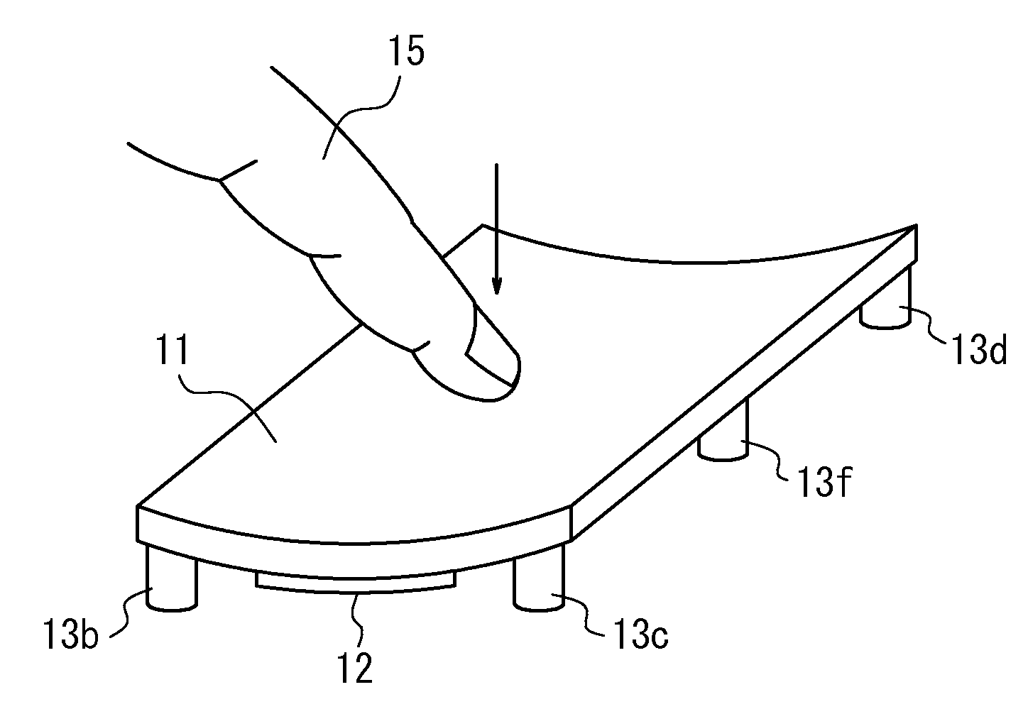
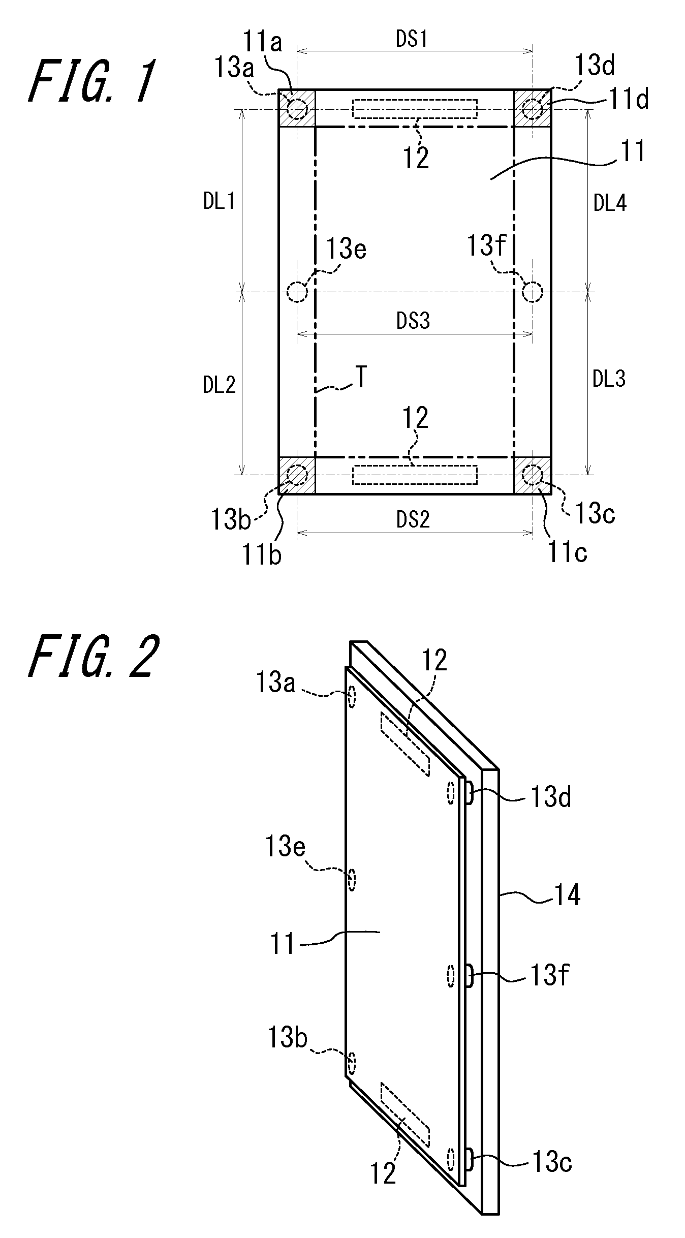
[0033]FIGS. 1 and 2 are a plan view and a perspective view schematically illustrating the structure of a touch panel apparatus according to an embodiment of the present invention. The touch panel apparatus according to the present embodiment includes an oblong touch panel 11. While the example of the oblong touch panel 11 in FIG. 1 is rectangular, an oblong shape in this description is not limited to being rectangular, but also includes a shape with rounded corners.

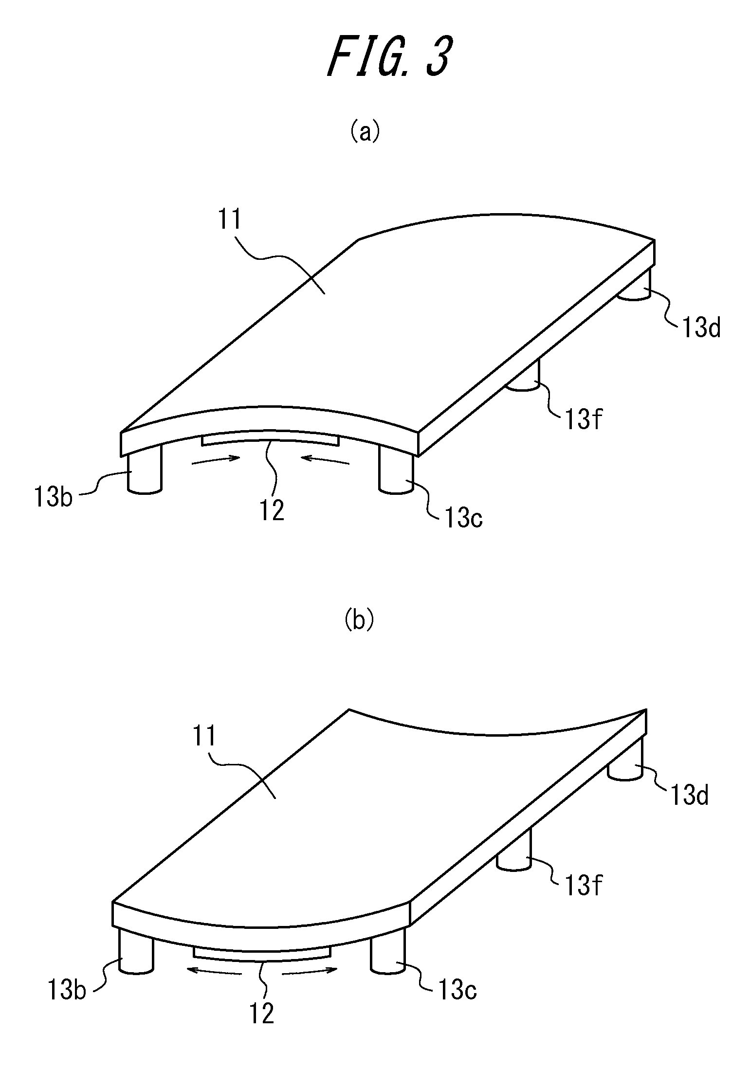
[0034]At the back, near the short ends of the touch panel 11, a piezoelectric element 12 is provided along each short end. Each of the piezoelectric elements 12 is formed from monomorph, bimorph, unimorph, or the like, and one side is adhesively secured to the touch panel 11 so as to be able to expand and contract in the short side direction of the touch panel 11.

[0035]So that the bending direction due to a target be...


PUM


Abstract

A touch panel apparatus includes a touch panel (11), a piezoelectric element (12) disposed on the touch panel (11) and capable of expansion and contraction, and a plurality of support members (14a-14f) disposed on a fixing portion (13) and configured to support and allow for flexure vibration of the touch panel (11), such that the support members (14a-14f) are disposed in greater number in a direction orthogonal to an expansion and contraction direction of the piezoelectric element (12) than in the expansion and contraction direction so that a bending direction of the touch panel (11) due to a press matches a flexure direction of the touch panel (11) due to the expansion and contraction of the piezoelectric element (12).

Description

CROSS-REFERENCE TO RELATED APPLICATION[0001]This application claims priority to and the benefit of Japanese Patent Application No. 2010-236775 filed Oct. 21, 2010, the entire contents of which are incorporated herein by reference.TECHNICAL FIELD[0002]The present invention relates to a touch panel apparatus.BACKGROUND ART[0003]In recent years, a variety of input apparatuses have been proposed in which piezoelectric elements are provided in a touch panel. When a user's finger, a stylus pen, or the like presses a target in a predetermined area of the touch panel, the input apparatuses detect input of the press and drive the piezoelectric elements, thus vibrating the touch panel so as to provide the user with an appropriate operational feeling. In a known touch panel apparatus, for example as illustrated in FIG. 8, at the back of each of the long sides of an oblong touch panel 51, a piezoelectric element 52 capable of expansion and contraction is disposed in the long side direction. The...

Claims


Application Information

Patent Timeline
Patent Type & Authority Patents(United States)
IPC IPC(8): G06F3/041G06F3/01
CPCG06F3/041G06F3/016
Inventor TAKEDA, JUNKONO, KENJIAONO, TOMOTAKE
Owner KYOCERA CORP
Why Eureka
Try Eureka