Suspension system having a leaf spring

a suspension system and leaf spring technology, applied in the direction of resilient suspensions, interconnection systems, vehicle springs, etc., can solve the problems of creating more extreme conditions for suspension systems and relatively harsh ride quality

Active Publication Date: 2015-06-09
HENDRICKSON USA L L C
View PDF19 Cites 13 Cited by
  • Summary
  • Abstract
  • Description
  • Claims
  • Application Information

AI Technical Summary

Benefits of technology

[0012]In a third aspect, disclosed herein is a method of controlling roll stiffness in a suspension system for a vehicle that includes providing a leaf spring having an axle seat portion having tapered upper and lower surfaces, a front limb having a vertical spring rate and a length that extends forward from the axle seat portion to a front end and a rear limb having a vertical spring rate and a length that extends rearward from the axle seat portion to a rear end. The method also includes providing couplings that connect the front and rear ends of the leaf spring to a vehicle frame member and providing an axle coupling assembly that couples a vehicle axle to the axle seat portion of the leaf spring. The method further includes providing a bumper disposed between the leaf spring and the vehicle frame member, and wherein a center of the bumper is located forward and inward of a center of the axle coupling assembly, such that when the suspension is in a roll condition and the bumper is engaged and compressed, roll stiffness of the leaf spring is increased.
[0013]The present disclosure includes examples of suspension systems, leaf springs and methods of controlling roll stiffness that include use of a leaf spring having relatively low mass and a relatively low vertical spring rate for improved ride comfort, while also including a bumper that increases stiffness during roll and contributes to improved management of rear limb windup during braking. The leaf spring may be constructed with a combination of front to rear limb length ratio and spring rate ratio that provide the leaf spring with almost constant caster, despite having asymmetrical limb lengths. The leaf spring alternatively may be constructed to have an equal limb length ratio. Tapering of the upper and lower surfaces of the leaf spring in the axle seat portion acts as a longitudinal retention for the leaf spring within the axle coupling assembly. Having a maximum thickness in the axle seat portion contributes to lower assembly stress and may reduce chances of hydrogen assisted cracking, while the bumper assists in handling jounce, rear limb windup, and roll stiffness.
[0014]The leaf spring and axle coupling assembly do not include a center hole and bolt therethrough, helping to reduce potential stresses and the risk of leaf spring fracture. Instead, a less invasive locator may be used to help keep the leaf spring properly located within the axle coupling assembly. The lack of a hole through the axle seat portion of the leaf spring also allows more of the leaf spring to be active.
[0015]The upper and lower surface tapers in the forward region of the axle seat portion help to reduce mass, the overall vertical rate of the spring and the stress on the front parabola, in the examples provided, by removing low stressed material, where the overall thickness required at the center of the axle seat portion may be defined by the rear limb parabola in the examples, instead of the front. The rearward region of the axle seat portion also is tapered, reducing mass, adding extra longitudinal retention of the leaf spring and helping to balance the forces within an installed axle coupling assembly. When used with an axle coupling assembly having a closer clamping fastener pattern, more of what traditionally would have been the inactive axle seat portion of the leaf spring can be active. This permits increased leaf spring effectiveness, while allowing further reductions in the material and weight of the leaf spring and of the axle coupling assembly.
[0016]Inclusion of the bumper increases the roll stiffness in a dynamic maneuver. Location of the bumper forward of the center of the axle coupling assembly assists in balancing the stress between the front and rear limbs of the leaf spring during jounce and vehicle braking. Location of the bumper forward of and offset from the center of the axle coupling assembly also allows the use of the rear limb to add roll rate by causing more twist in the rear limb, and increased vertical rate via rear limb windup. This is made possible with a single leaf spring, or monoleaf, having a relatively low stress rear limb.
[0017]Prior art suspension systems that utilize a monoleaf configuration carry extra weight in steel where it is not needed to manage the stresses and tend to rely completely on the leaf spring to build roll stiffness into the suspension system at the cost of ride quality. This problem has been exacerbated by the mandates for decreased stopping distances which, in turn, further increase the stresses in the leaf spring and suspension system. Thus, the present disclosure presents examples of suspension systems, leaf springs and methods that overcome disadvantages of the prior art and may be used to reduce mass and to help control jounce, rear limb windup and roll, while controlling the limb spring rates and roll stiffness in a suspension system. This, in turn, provides lower unsprung mass, less vertical spring stiffness, and therefore, more comfort under normal driving conditions.

Problems solved by technology

With the advent of new laws regarding braking capabilities of vehicles, such as heavy duty trucks, forces and stresses experienced in suspension systems during hard braking are creating more extreme conditions for suspension systems.
However, such a configuration with a massive axle seat portion, substantial thickness and a relatively high spring rate within the limbs of the leaf spring results in heavy springs that also produce relatively harsh ride quality.

Method used


Image

  • Suspension system having a leaf spring
  • Suspension system having a leaf spring
  • Suspension system having a leaf spring

Examples


Embodiment Construction

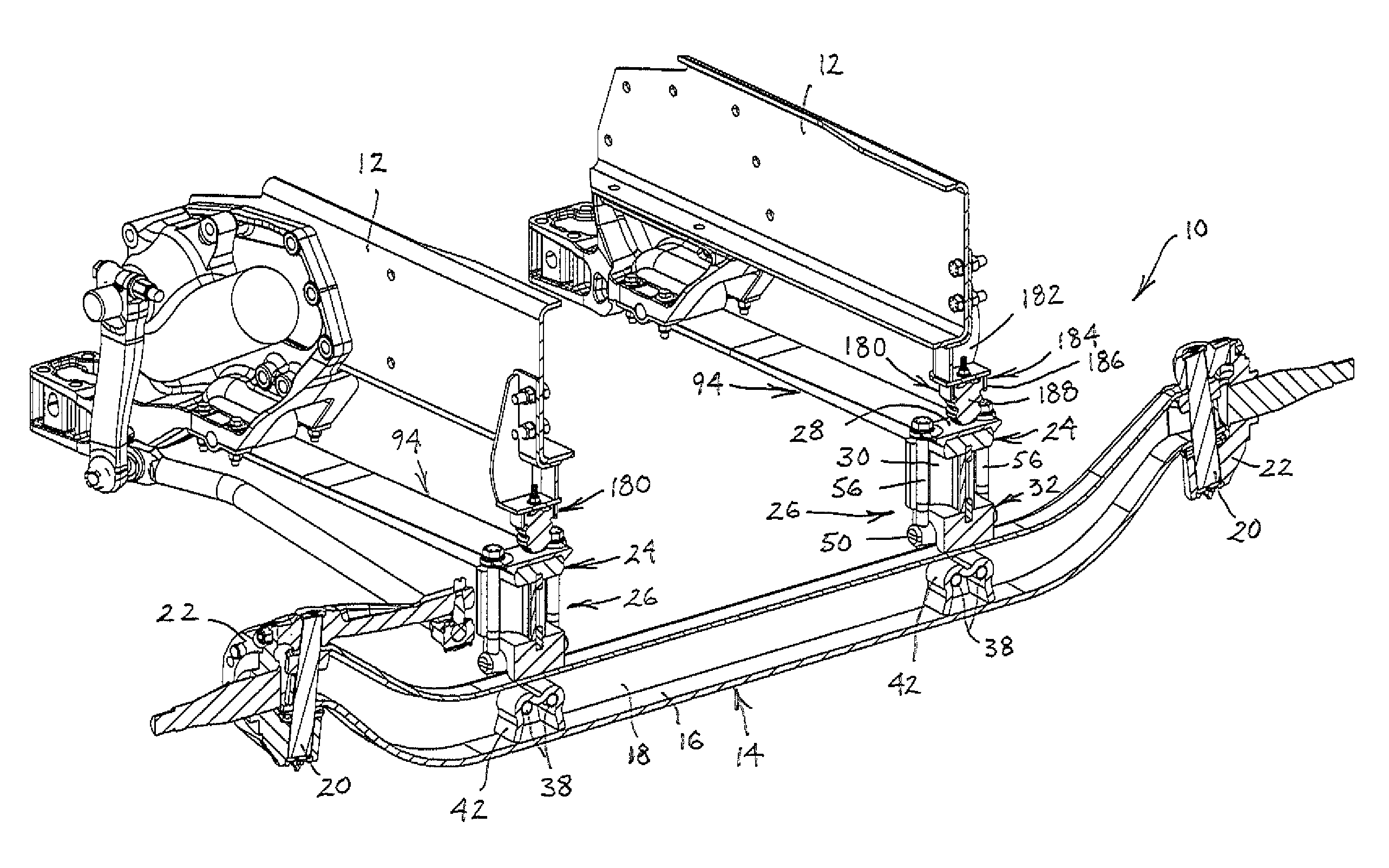
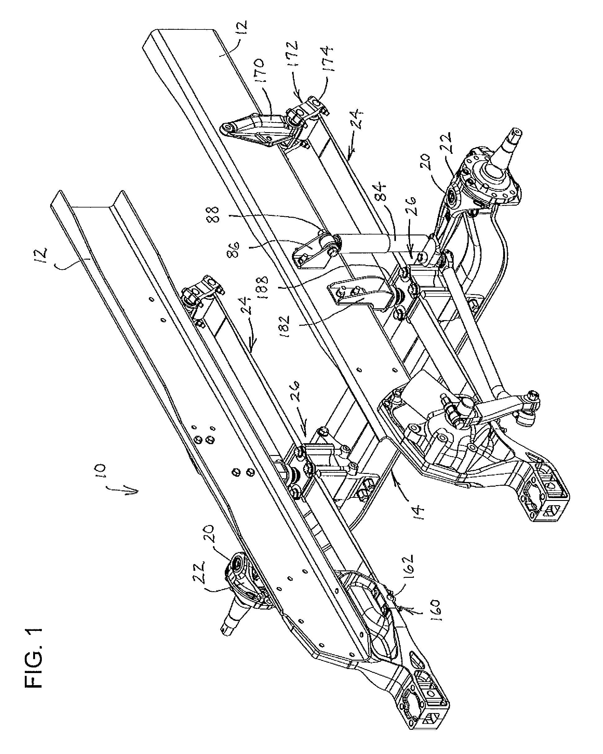
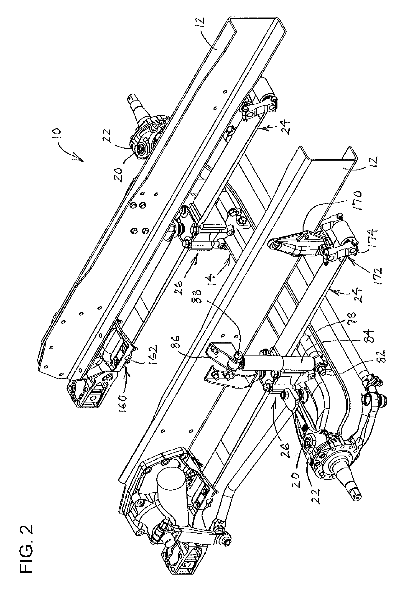
[0040]This disclosure presents examples of suspension systems, leaf springs for use in suspension systems and methods of controlling jounce and roll stiffness in vehicles, which may be embodied in several forms. For instance, in a first example, a vehicle suspension system is configured with the leaf spring of the present disclosure being coupled to a vehicle axle using a special axle coupling assembly that provides improved fastener engagement, and a bumper that is coupled to a frame member of the vehicle. It will be appreciated that, as shown in a further example, the suspension system could instead have the bumper coupled to the axle coupling assembly. As shown in yet a further example, it will be appreciated that the leaf spring of the present disclosure could be used with different axle coupling assemblies, and the leaf spring and suspension system may include variations as desired to suit particular installations and vehicle characteristics.

[0041]Turning to FIGS. 1-10, a first...


PUM


Abstract

Suspension systems, leaf springs and methods of providing a leaf spring in a suspension system are disclosed. The suspension systems, leaf springs and methods of providing a leaf spring in a suspension system allow use of a lighter weight leaf spring while providing customized roll stiffness and vertical spring rate that are complemented by a bumper that engages the leaf spring assembly when compressed to at least a preselected position.

Description

CROSS-REFERENCE TO RELATED APPLICATION[0001]This application claims the benefit of U.S. Provisional Patent Application Ser. No. 61 / 680,156, filed Aug. 6, 2012, the disclosure of which is hereby incorporated by reference in its entirety.BACKGROUND OF THE INVENTION[0002]1. Field of the Invention[0003]The present invention generally relates to a leaf spring and a suspension system employing a leaf spring for use in a vehicle. This disclosure presents several example embodiments that may be utilized for particular purposes.[0004]2. Discussion of the Prior Art[0005]Wheeled vehicles commonly have suspension systems that utilize springs to suspend a body assembly above the axles to which wheels are rotatably connected. In this context, the body assembly generally is referred to as the sprung portion of the vehicle and the wheels and respective axles, whether dealing with independent suspensions or solid axle suspensions, generally are referred to as the unsprung portions of the vehicle. Fo...

Claims


Application Information

Patent Timeline
Patent Type & Authority Patents(United States)
IPC IPC(8): B60G21/05B60G11/04B60G9/00B60G11/38
CPCB60G11/04B60G9/003B60G11/38B60G2202/112B60G2202/143B60G2204/4306B60G2204/4502
Inventor DILWORTH, DAMON E.RAREY, ANDREW X.LUMETTA, SAMMY C.DUDDING, ASHLEY T.
Owner HENDRICKSON USA L L C
Why Eureka
Try Eureka