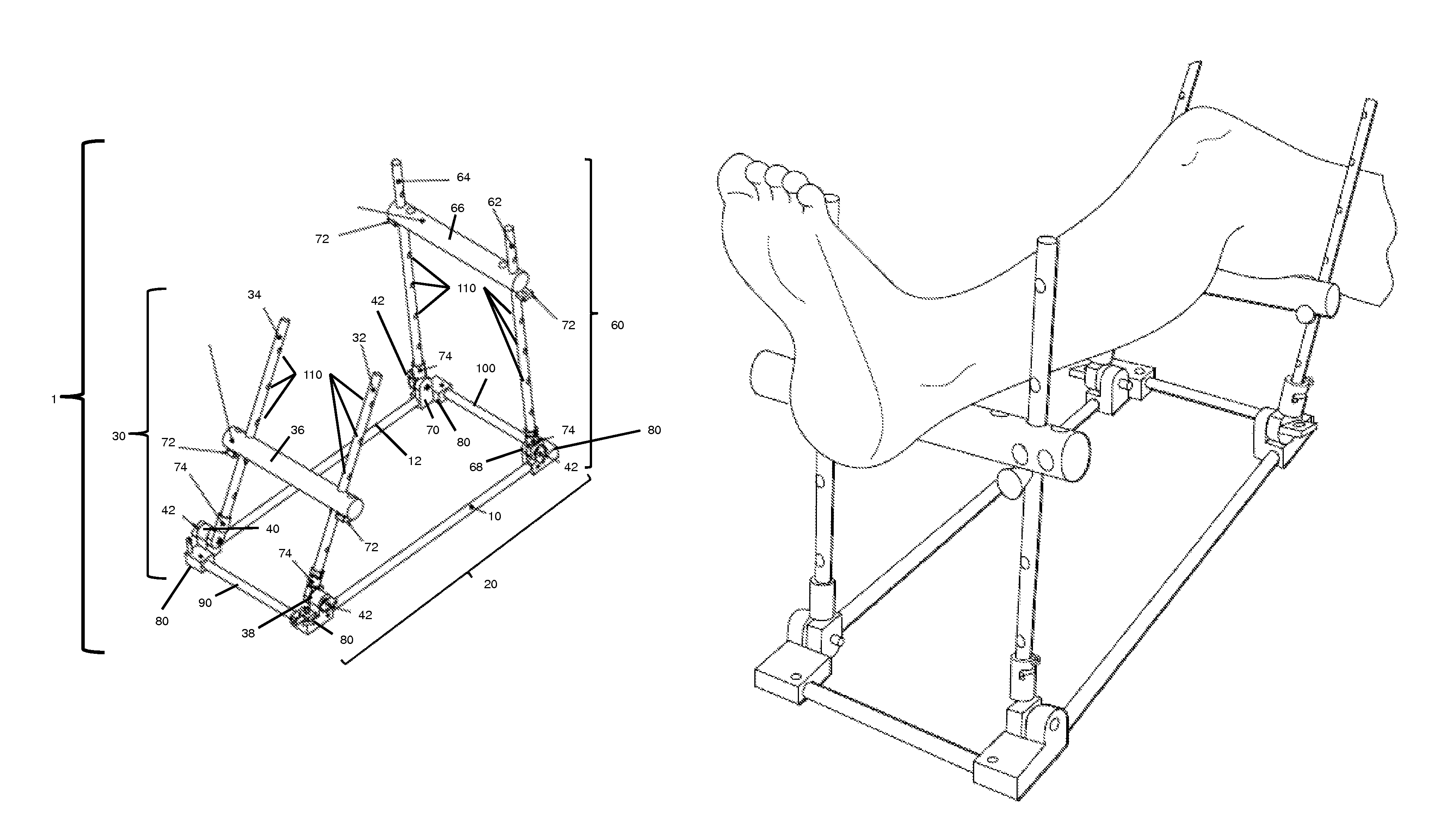
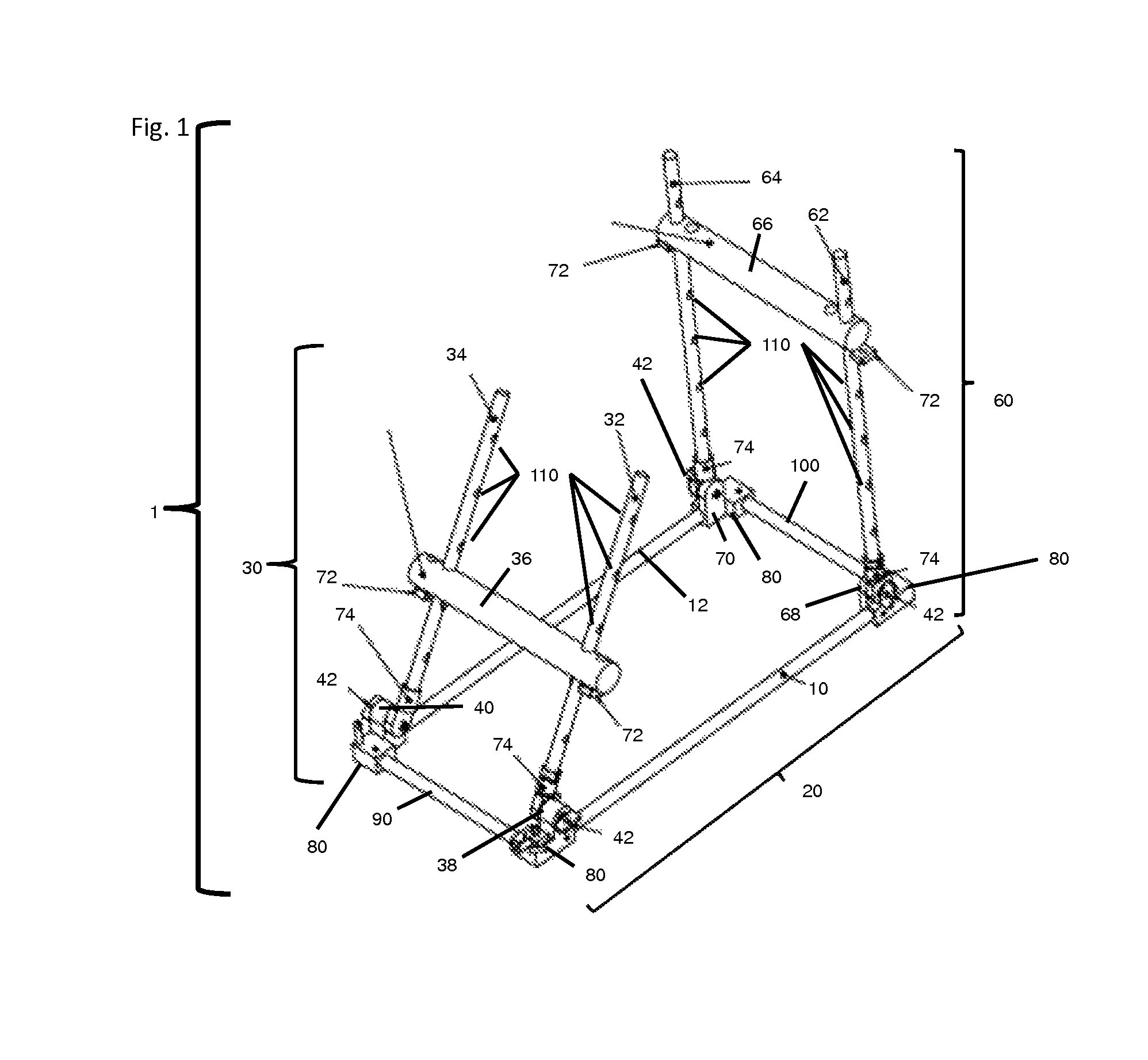
Limb positioner

a technology of limb positioner and limb support, which is applied in the field of limb positioner, can solve the problems of limiting the therapeutic value of some patients and medical professionals, the device known in the art for supporting the limb of a patient cannot be easily disassembled or collapsed for transport or storage, and the lack of full access to the limb area, etc., to achieve the effect of easy storage and transportation, increased or decreased distance between the first and second limb support structures along the first and second

Active Publication Date: 2015-06-16
INNOVISION CO LTD
View PDF35 Cites 10 Cited by
  • Summary
  • Abstract
  • Description
  • Claims
  • Application Information

AI Technical Summary

Benefits of technology

[0013]In yet other embodiments, one or more of the first, second, third, and fourth raised supports are rotatably connected to the base supports by limb support structure connectors that can be movable, rotatable, or both. The limb support structure connectors can allow movement of the raised supports along the length of the first and second base supports, such that the distance between the first and second limb support structures along the first and second base supports can be increased or decreased. The limb support structure connectors can also allow rotation of the raised supports relative to the first and second base supports (e.g., the angle between the raised supports and the base structure can be increased or decreased). For example, the limb support structure connectors allow rotation of the first and second limb support structures toward or away from the plane defined by the base structure. By rotating the first and second limb support structures using the limb support structure connectors, the first and second limb support structures can be oriented relative to the first and second base supports at an angle from about 0° to about 180° (e.g., an angle of about 30°, 50°, 70°, 90°, 100°, 120°, 140°, 160°, and 180° between the plane of a limb support structure and the plane of the base structure). In particular, the first and second limb support structures arc configured so that they can rotate into an interior region of the base structure (e.g., to produce a substantially flat, collapsed structure that can be easily stored and transported; see, e.g., FIG. 4). The interior region of the base structure may be defined as the region between the first and second base supports and, if third and fourth base supports are present, the interior region may be further defined as the region between the first, second, third, and fourth base supports.
[0014]In other embodiments, the limb support structure connectors of the raised supports can be tightened to prevent movement, rotation, or both of the raised supports of the first and second limb support structures when the device is in use, e.g., during support of the limb of a patient. If desired, the limb support structure connectors of the raised supports can be loosened to allow movement of the raised supports along all or a portion of the length of the first and second base supports. For example, when the limb support structure connectors of the first and second raised supports are loosened, the first limb support structure can be moved toward or away from the second limb support structure by pushing the first and second raised supports along the first and second base supports. Once the first limb support structure is located at the desired position, the limb support structure connectors of the first and second raised supports can be retightened. Alternatively, the limb support structure connectors of the first and second raised supports can be loosened such that the first limb support structure is completely disengaged from the first and second base supports. The first limb support structure can then be restored to a position on the first and second base supports by fitting the ends of the first and second raised supports that were previously connected to the first and second base supports via the limb support structure connectors and retightening the limb support structure connectors (e.g., by hand or by tool) to firmly secure the limb support structure to the base structure.
[0021]In other embodiments, the first and second limb support bars are attached to the raised supports by releasable connectors, each of which can be independently engaged and disengaged to allow movement of the first and second limb support bars along the length of the raised supports. When engaged, the releasable connectors prevent movement of the limb support bars, e.g., when pressure is applied to the limb support bar by, e.g., the weight of a limb of a patient. To move the limb support bar, the releasable connectors at one or both ends of the limb support bar are disengaged and the limb support bar is moved along the raised support(s) to a desired height. The releasable connectors can be reengaged to secure the limb support bar at the chosen height. The releasable connectors can be configured so that, once disengaged, the limb support bars of the device of the invention can be completely separated from the device. Alternatively, the releasable connectors can be configured so that, once disengaged, the limb support bars of the device of the invention can move freely up and down the raised supports, but cannot be completely separated from the device.

Problems solved by technology

Many of the supports, though, are not adjustable, which limits their therapeutic value to some patients and medical professionals.
Of those supports that allow some adjustment, there is generally a lack of full access to areas of the limb during the performance of medical procedures.
In addition, some devices known in the art for supporting the limb of a patient cannot be easily disassembled or collapsed for transport or storage and generally cannot be easily sterilized.
Devices currently in use do not satisfactorily meet the need for a limb positioner that is adjustable and that provides easy and full 360° access to desired portions of a patient's limb, such as the patient's knee and portions of the leg surrounding the knee, during, e.g., surgery, evaluation, or rehabilitation.

Method used


Image

  • Limb positioner
  • Limb positioner
  • Limb positioner

Examples


example 1

Use of a Positioner Device of the Invention to Repair a Fracture or Other Bone or Tissue Defect

[0110]A positioner device of the invention can be used to provide fracture support, e.g., for a subarticular fracture, in conjunction with conventional fixation. The positioner allows for the extremity to be placed at different angles and heights creating an optimal workspace for fixation. The positioner allows for proper alignment of a fracture prior to fixation. The positioner also allows for greater access to a patient's extremity during fixation (e.g., the positioner does not obstruct the physician's access to the extremity during bone or fracture repair procedures).

example 2

Use of a Positioner of the Invention in Conjunction with Reattachment of Ligaments or Tendons

[0111]A positioner of the invention can be used to provide support and proper positioning of the limb of a patient during surgery to reattach a torn ligament or tendon. The positioner can be used to adjust the height of the patient's limb to provide easy access for the surgeon to the area in need of attention. The positioner can also be used to place the limb in a comfortable position for the patient.

example 3

Use of a Positioner of the Invention for Anterior Cruciate Ligament (ACL) Reconstruction

[0112]A positioner of the present invention can be used to position and support a patient's leg so that the patient's knee is easily accessible to the surgeon during surgery on, or replacement of, the ACL following a tear.


PUM


Abstract

The invention features devices for positioning and supporting the limb (e.g., an arm or leg) of a patient. The devices provide adjustable support for, e.g., the upper and lower leg. In addition, the device provides unfettered access to the patient's extremities and joints (e.g., the knee and portions of the leg above and below the knee). The invention further features methods of using the devices during diagnostic review, surgery, and rehabilitation. In addition, the invention features methods of treating a patient having a bone or tissue defect by using a device described herein.

Description

CROSS-REFERENCE TO RELATED APPLICATIONS[0001]This application is the U.S. National Stage filing under 35 U.S.C. §371 of International Application No. PCT / US2011 / 027660, filed Mar. 9, 2011, which claims benefit of U.S. Provisional Application No. 61 / 311,849, filed Mar. 9, 2010.FIELD OF THE INVENTION[0002]The invention relates to devices for positioning the extremity of a patient, in particular, a patient's leg or arm, during medical procedures, such as surgery, evaluation, or rehabilitation, and methods of use thereof for the treatment of bone or tissue defects.BACKGROUND OF THE INVENTION[0003]Many surgical procedures require that a patient's limb or limbs be placed in a number of different positions for the performance of the surgical procedure. It is desirable that the operating surgeon or surgical assistant be able to move the limb into positions and configurations that may be required during the course of the surgical procedure. It is also desirable that any positioning apparatus...

Claims


Application Information

Patent Timeline
Patent Type & Authority Patents(United States)
IPC IPC(8): A61G13/12
CPCA61G13/1245A61G13/124A61G13/1235A61G7/0755
Inventor RUSSELL, THOMAS A.
Owner INNOVISION CO LTD
Why Eureka
Try Eureka