
Radar operation with increased doppler capability

a technology of doppler capability and radar, applied in the field of radar systems, can solve the problems of reducing the unambiguous range capability, the method cannot characterize the complex spectra encountered in tornadoes, and the weather radar cannot characterize the velocity presen

Active Publication Date: 2015-06-16
LASSEN RES CORP
View PDF29 Cites 31 Cited by
  • Summary
  • Abstract
  • Description
  • Claims
  • Application Information

AI Technical Summary

Benefits of technology

The patent describes a method for using reflections of wave energy to characterize objects through spectral analysis. The method involves generating a repeating sequence of constant-frequency pulses with a particular constant phase, and then modulating the phase of the echo energy reflected from the objects during each receiving subinterval by the same quadratic phase sequence used for the transmitted pulses. The net phase modulation results in a difference between the phase of the transmitted pulses and the reflected echo energy, which can be measured in discrete units of time. The method can produce a composite signal frequency spectrum by translating the received echo energy into a different frequency range. The technical effect of this patent is to provide a reliable and accurate way to characterize objects using wave energy reflections.

Problems solved by technology

The technical problem addressed by this patent is how to improve the ability of weather radar systems to accurately measure the speed and distance of objects in severe weather conditions like tornados. Current limitations prevent them from doing so with certainty.

Method used


Image

  • Radar operation with increased doppler capability
  • Radar operation with increased doppler capability
  • Radar operation with increased doppler capability

Examples


Embodiment Construction

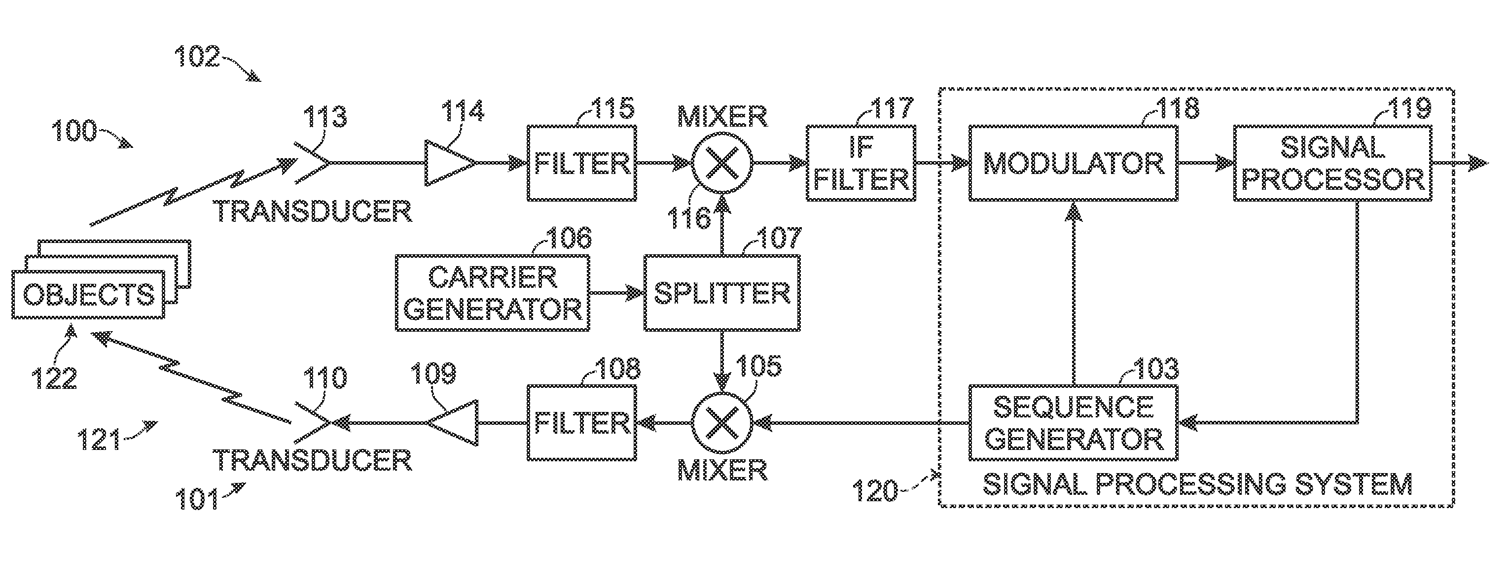
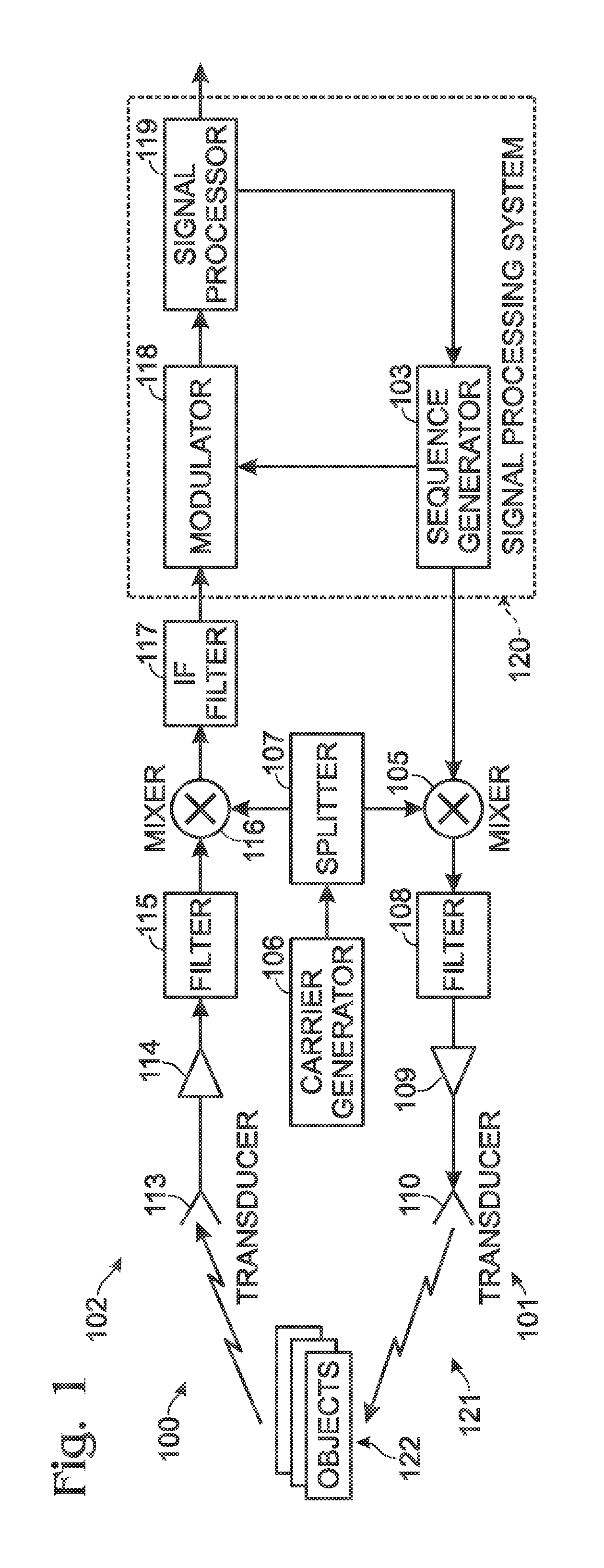
[0030]Systems and methods are disclosed herein for echo-ranging simple or complex objects, whereby characteristics of echoes can be analyzed in a spectral domain to provide information on location, echo intensity, radial velocity, relative motion, and / or other properties of the objects.

[0031]FIG. 1 is a block diagram of an exemplary generalized system, shown generally at 100, for such echo-ranging with mono-static, bi-static, and / or multi-static operation. Echo-ranging system 100 may include a transmitter 101 and a receiver 102. Transmitter 101 may include an intermediate frequency (IF) sequence generator 103, a mixer 105, a carrier generator (or carrier frequency oscillator) 106, a splitter 107, a filter 108, an amplifier 109, and a signal transducer 110. Receiver 102 may include a transducer 113, an amplifier 114, a filter 115, a mixer 116, an IF filter 117, a modulator (e.g., a quadrature demodulator) 118, and a signal processor 119. In this example, the transmitter and receiver ...


PUM


Abstract

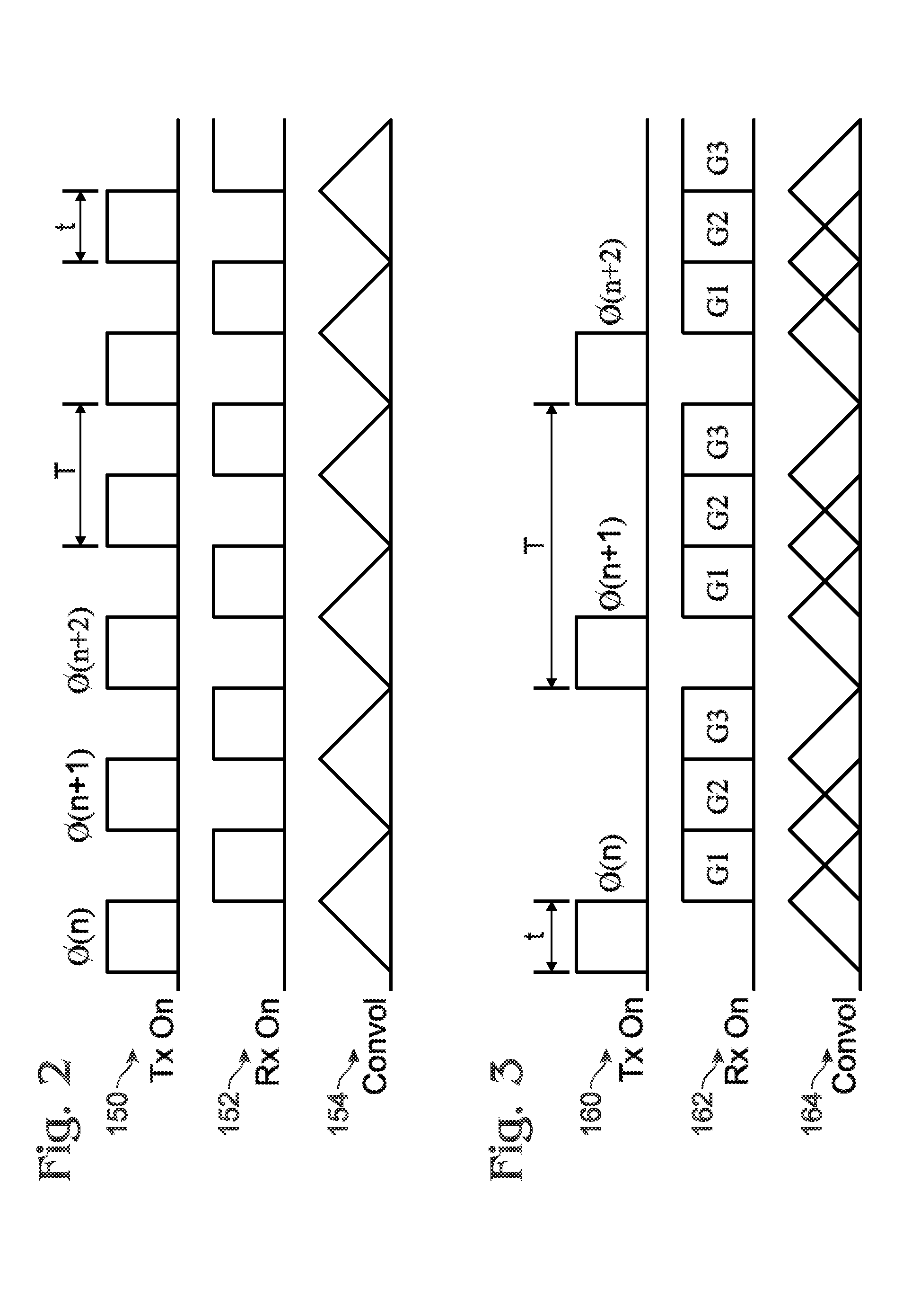
A method may include generating for transmission a repeating sequence of N constant-frequency pulses of width t seconds at interpulse intervals of T seconds, with each pulse in the sequence having a particular constant phase according to a quadratic phase sequence, which phase is applied to each pulse in a first sense of modulation. The method may further include modulating the phase of echo energy received from one or more objects reflecting the transmitted repeating sequence of N constant-frequency pulses with a second sense of modulation opposite to the first sense of modulation. The method may further include producing from the modulated received echo energy N unique and discrete frequency translations of the received echo energy as a function of range r of the reflecting objects, of magnitude equal to multiples of 1/NT Hz, which may preserve the spectrum of the received echo energy, forming in combination a composite signal frequency spectrum.

Description


Claims


Application Information

Patent Timeline
Owner LASSEN RES CORP
Learn More