Digital multiphase hysteretic point-of-load dc/dc converter

a dc/dc converter, digital multiphase technology, applied in the direction of dc-dc conversion, power conversion system, pulse automatic control, etc., can solve the problems of power efficiency, thermal management becomes an issue, voltage regulation and current sharing among each phase, and the switching frequency synchronization is difficult, so as to achieve superior transient response and superior recovery time

Active Publication Date: 2018-02-15
ARIZONA STATE UNIVERSITY +1
View PDF1 Cites 51 Cited by
  • Summary
  • Abstract
  • Description
  • Claims
  • Application Information

AI Technical Summary

Benefits of technology

[0012]While some analog elements may be retained in the circuit, because the output quantity of interest is an output voltage as is the input reference, the use of high speed error-corrected comparators rather than slow “op amp” error amplifiers achieves superior transient response and much superior recovery time from and resilience against single event transient output errors (a key concern for load devices' own reliability and consistency of operation).
[0013]Full load efficiency matches commercial competitors even in an inferior “package of convenience” and is optimized by use of phase shedding which cuts switching losses by 25-75% depending on load-point. A 4-phase set of integrated power switch devices is capable of delivering up to 10 A of DC current.

Problems solved by technology

Although a single-phase DC-DC converter works well for low current applications, power efficiency and thermal management become an issue when the peak current of the application processors (APs) reaches several amperes or more.
However, switching frequency synchronization, voltage regulation and current sharing among each phase are challenging.
However, they cannot be synchronized to a reference switching frequency [1], or only cancel the output voltage error induced by the inductor DC resistance (DCR-IE) [4], or are not able to achieve current balancing because the duty cycle is not calibrated for slave phases [1,3].

Method used


Image

  • Digital multiphase hysteretic point-of-load dc/dc converter
  • Digital multiphase hysteretic point-of-load dc/dc converter
  • Digital multiphase hysteretic point-of-load dc/dc converter

Examples


Embodiment Construction

[0049]In the following description of the preferred embodiment, reference is made to the accompanying drawings which form a part hereof, and in which is shown by way of illustration a specific embodiment in which the invention may be practiced. It is to be understood that other embodiments may be utilized and structural changes may be made without departing from the scope of the present invention.

[0050]Technical Description

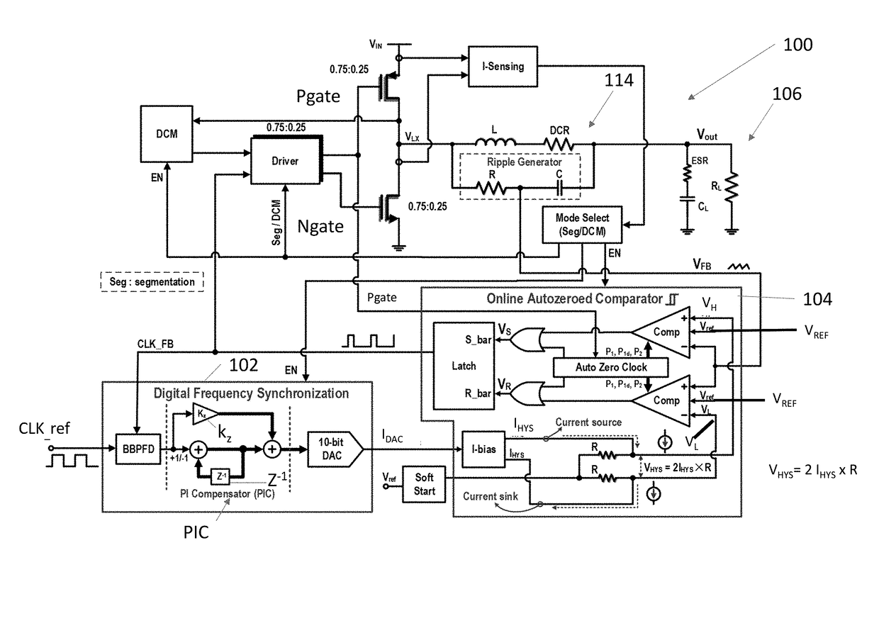
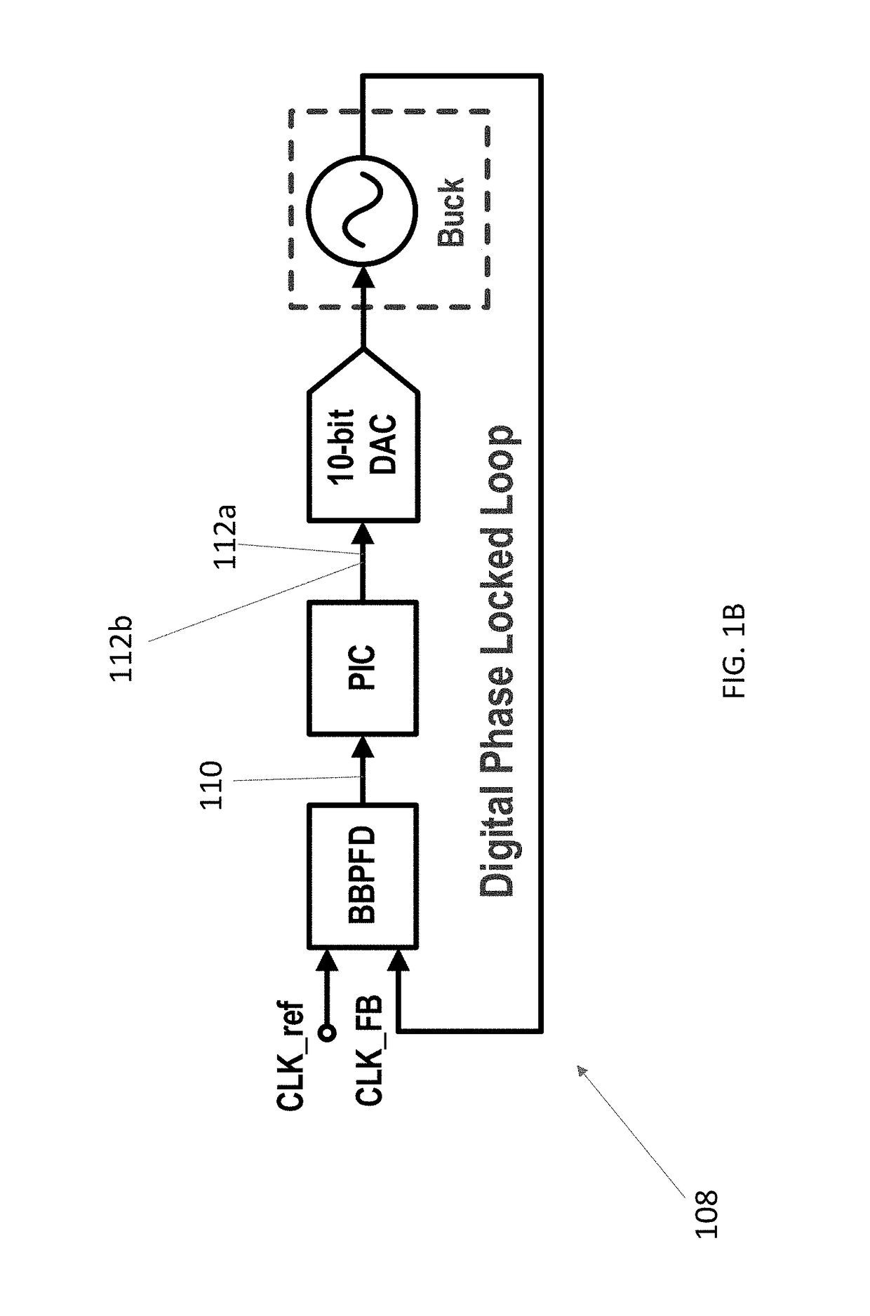
[0051]The present disclosure describes a single or multi-phase hysteretic quasi-current-mode DC / DC (e.g., buck) converter. By employing a digital frequency synchronization (DFS) method to tune the hysteretic window, the converter is easily synchronized, e.g., within ±1.5% of the input reference clock, and hence shows a fixed switching frequency. By using an online auto zero (OAZ) topology, the hysteretic comparator input referred offset is canceled so that converter output voltage error is, e.g., within ±1% of the input voltage reference. By applying a duty-cycle-...


PUM


Abstract

An autozeroed comparator controls a frequency fsw of the input voltage inputted to a DC/DC converter. A digital frequency synchronization circuit is connected to the autozeroed comparator so as to form a phase locked loop, wherein the DES circuit controls the hysteretic window of the autozeroed comparator so as to lock fsw to a clock reference frequency. A plurality of slave phase circuits may be connected to the master phase circuit including the DFS circuit and the autozeroed comparator. Duty cycle calibration circuits adjust a duty cycle signal applied to each of the slave phase circuits, in response to average current measured in the slave phase circuits, so that each slave phase circuit is synchronized with the master phase circuit. A 6 A 90.5% peak efficiency 4-phase hysteretic quasi-current-mode buck converter is provided with constant frequency and maximum ±1.5% current mismatch between the slave phases and the master phase.

Description

CROSS REFERENCE TO RELATED APPLICATIONS[0001]This application claims the benefit under 35 U.S.C. Section 119(e) of co-pending and commonly-assigned U.S. Provisional Patent Application Ser. No. 62 / 372,458, filed on Aug. 9, 2016, by Philippe C. Adell and Bertan Bakkaloglu, entitled “DIGITAL MULTIPHASE HYSTERETIC POINT-OF-LOAD DC / DC CONVERTER”, (CIT-7588-P); which application is incorporated by reference herein.STATEMENT REGARDING FEDERALLY SPONSORED RESEARCH AND DEVELOPMENT[0002]The invention described herein was made in the performance of work under a NASA contract NNN12AA01C, and is subject to the provisions of Public Law 96-517 (35 USC 202) in which the Contractor has elected to retain title.BACKGROUND OF THE INVENTION1. Field of the Invention[0003]The present invention relates to DC / DC converters.2. Description of the Related Art[0004](Note: This application references a number of different publications as indicated throughout the specification by one or more reference numbers in ...

Claims


Application Information

Patent Timeline
Patent Type & Authority Applications(United States)
IPC IPC(8): H02M3/157H02M3/158
CPCH02M3/157H02M3/158H03L7/085H04B7/14H02M3/1563H02M3/1584H03L7/093
Inventor ADELL, PHILIPPE C.SUN, MINGBAKKALOGLU, BERTAN
Owner ARIZONA STATE UNIVERSITY
Why Eureka
Try Eureka