

Frequency-on-the-fly control circuit and method for a DC/DC PWM converter
a control circuit and converter technology, applied in the direction of electric variable regulation, process and machine control, instruments, etc., can solve the problems of poor efficiency and poor transient response, and achieve the effect of better efficiency and better transient respons
- Summary
- Abstract
- Description
- Claims
- Application Information
AI Technical Summary
Benefits of technology
Problems solved by technology
Method used
Image

Examples
Embodiment Construction
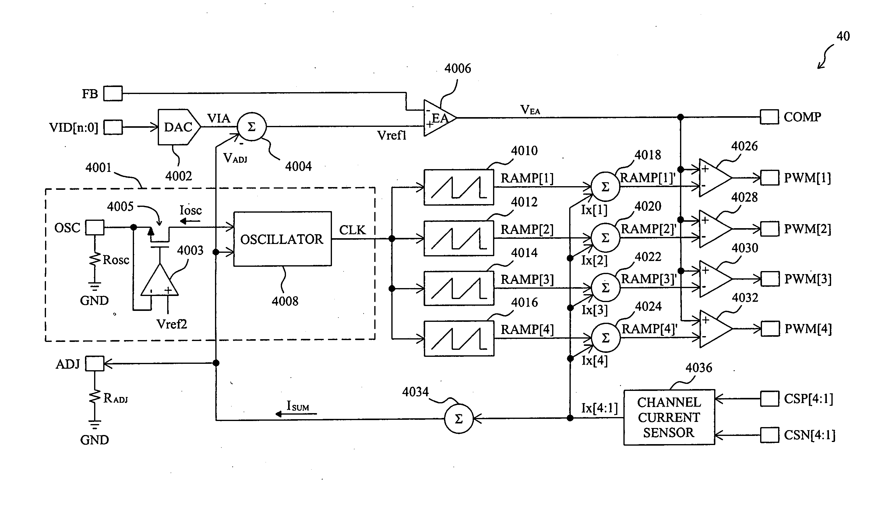
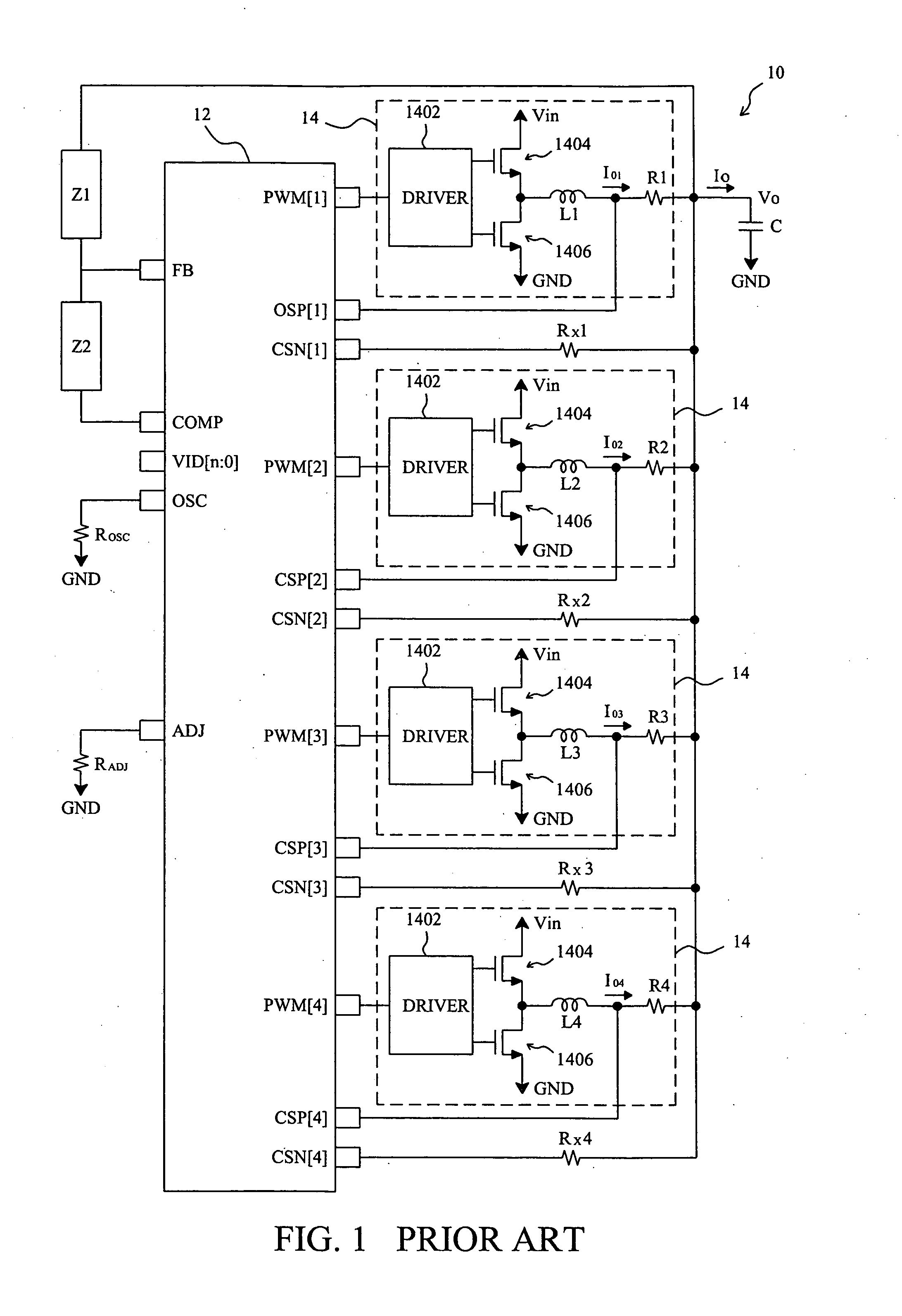
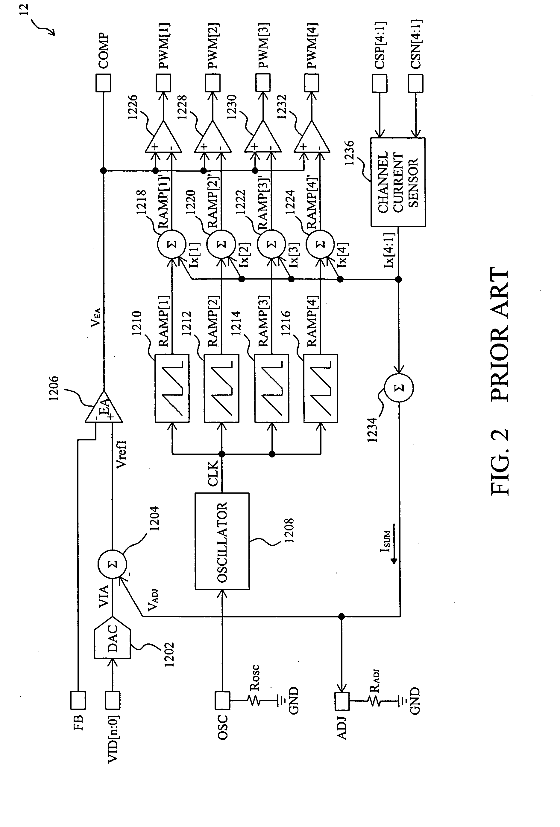
[0023]FIG. 6 shows an embodiment according to the present invention. For illustration, the control circuit 40 shown in FIG. 6 is designed for the control circuit 12 shown in FIG. 1 to implement the DC / DC PWM converter 10. In the control circuit 40, a channel-current sensor 4036 senses the channel currents IO1 to IO4 of the power stage 14 to produce four current-sensing signals Ix[1] to Ix[4] respectively, a combiner 4034 combines the current-sensing signals Ix[1] to Ix[4] to produce a summing signal ISUM which flows through a resistor RADJ to produce an adjusting voltage VADJ, and therefore the adjusting voltage VADJ changes with the output current IO of the DC / DC PWM converter 10 as VADJ=k 1×ISUM×RADJ=k 2×IO×RADJ=k 3×IO [Eq-3]
where k1, k2 and k3 are constant when the circuit parameters of the control circuit 40 are determined. A digital voltage signal VID[n:0] is converted to an analog voltage VIA by a DAC 4002, a combiner 4004 subtracts the adjusting voltage VADJ from ...
PUM
 Abstract
Description
Claims
Application Information