Automotive air blowers

Inactive Publication Date: 2010-04-27
DRIVETEC (UK) LTD +1
View PDF37 Cites 35 Cited by
  • Summary
  • Abstract
  • Description
  • Claims
  • Application Information

AI Technical Summary

Benefits of technology

[0026]It is preferred that the blower in accordance with the invention is so arranged that, at relatively low speed ratios of the air pump to the input from the engine, one of the electrical machines operates as a generator and produces electrical power, which is transmitted to the other electrical machine, which operates as a motor, and that, at relatively high speed ratios of the air pump, the other electrical machine operates as a generator and produces electrical power, which is transmitted to the one electrical machine, which operates as a motor. Thus in the preferred embodiment, at a constant input speed, the proportion of the input power transmitted between the two electrical machines progressively decreases, as the speed of the air pump increa

Problems solved by technology

If the engine is operating at high speed and a high inlet pressur

Method used


Image

  • Automotive air blowers
  • Automotive air blowers
  • Automotive air blowers

Examples


Embodiment Construction

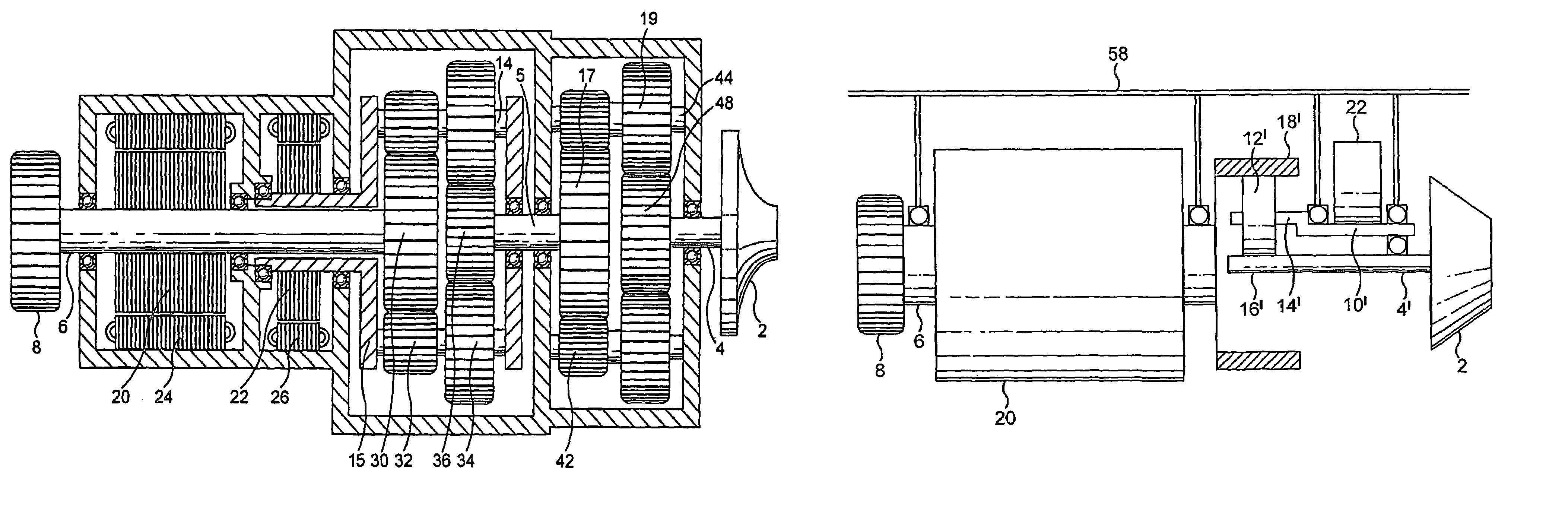
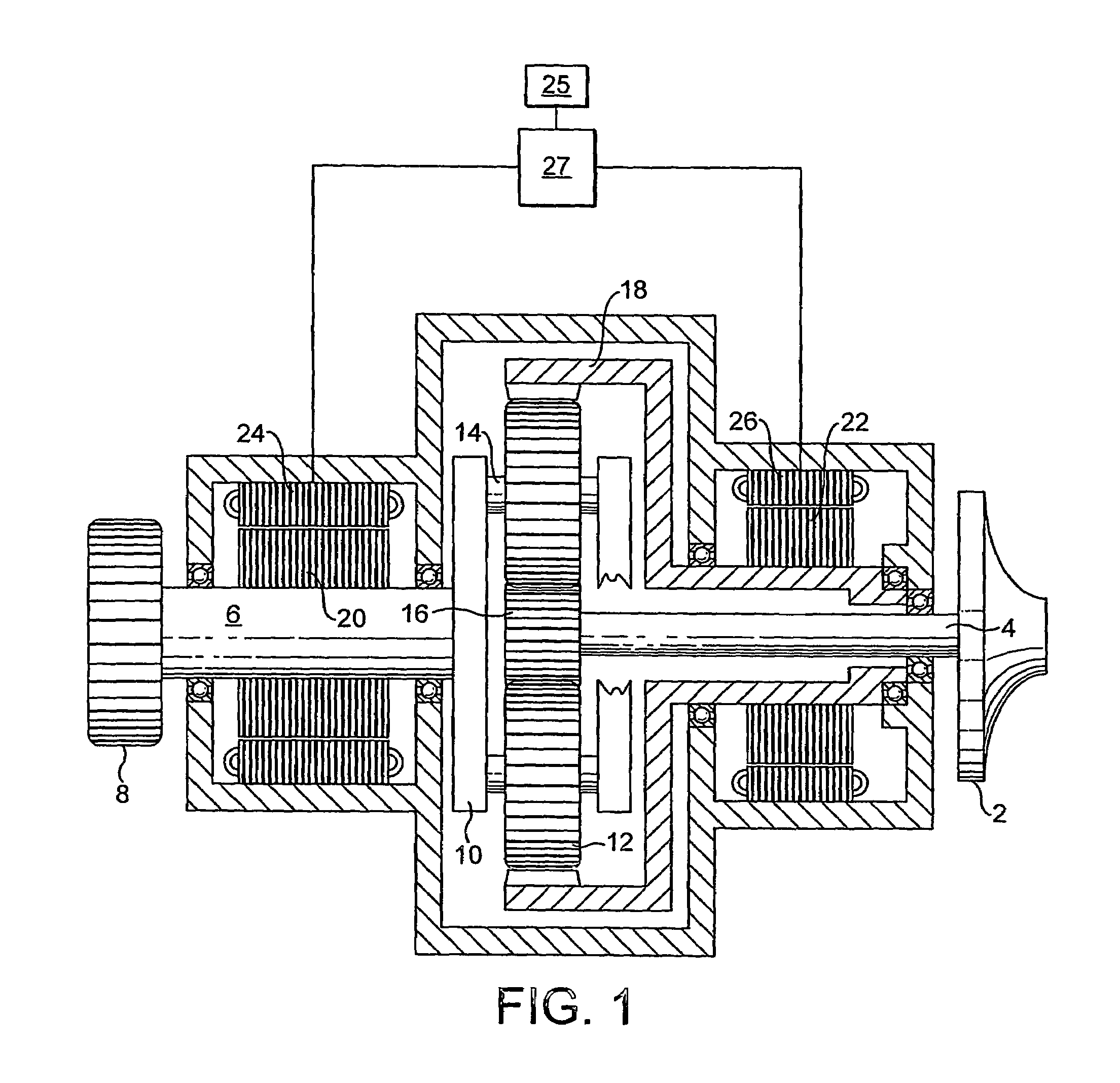
[0034]Referring firstly to FIG. 1, the supercharger includes an air pump 2 which, in which, in this case, constitutes a centrifugal air impeller which is situated, in use, in the inlet duct of an automotive engine. The impeller 2 is connected to the output shaft 4 of a transmission system, the input shaft 6 of which carries a pulley 8. In use, a pulley belt of known type will pass around the pulley 8 and round a further pulley driven by the engine and mounted on the engine crankshaft or some further shaft connected to be driven by the crankshaft. The two pulleys will typically be sized so as to produce a step-up ratio of the order of 3, whereby if the engine is rotating at, say, 1500 rpm, the imput shaft will be rotated at 4500 rpm.

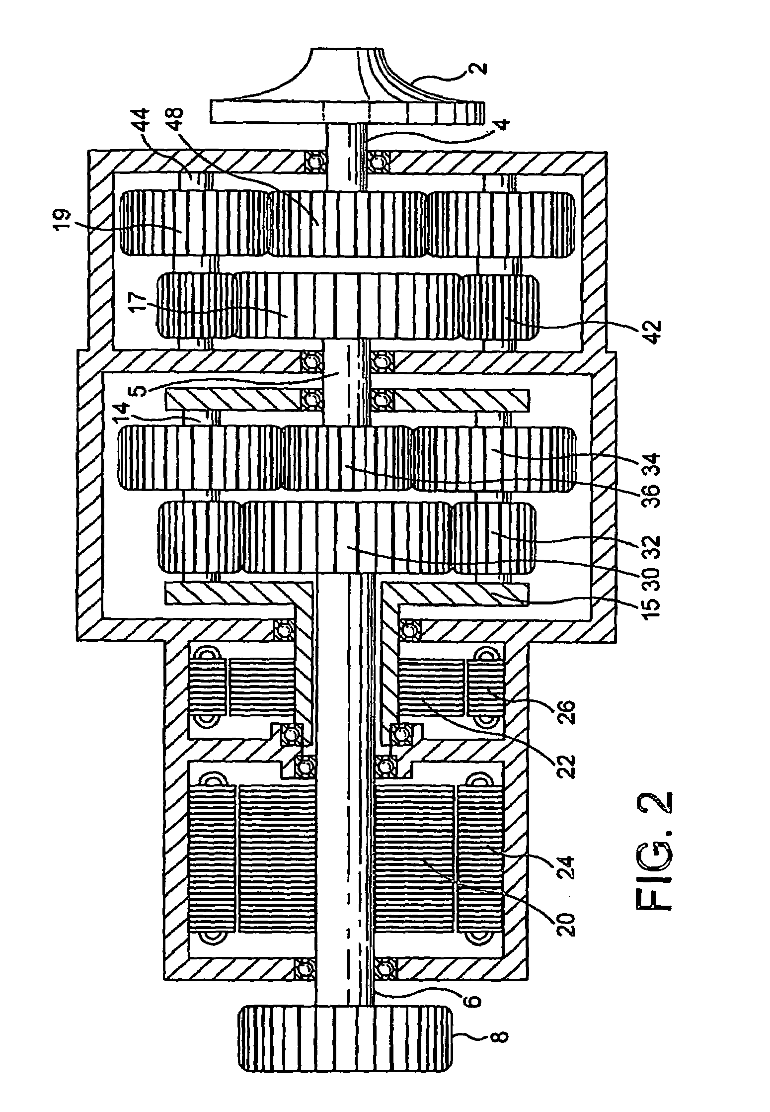
[0035]The transmission system comprises an epicyclic gearset of negative type. The input shaft 6 is connected to a carrier 10, which carries a number, typically three, of toothed planet wheels 12 which are rotatably mounted on respective planet shafts 14....


PUM


Abstract

An automotive air blower, in particular a supercharger, comprises an air pump, such as an air impeller (2) connected to the output shaft (4) of a transmission system, the input shaft of which is connected, in use, to the engine of a motor vehicle. The input and output shafts (6, 4) are connected to respective branches of a three-branch epicyclic differential gearset. The third branch of the gearset and the input shaft (6) are connected to the rotor (20, 22) of respective electrical machines, the electrical connections of the stators (24, 26) of which machines are connected together via a controller (27) arranged to control the flow of electric power between them.

Description

BACKGROUND OF THE INVENTION[0001]The present invention refers to automotive air blowers and, in particular to automotive superchargers, which are devices which may be incorporated in automotive engines. Superchargers are devices that include an air pump or blower wheel, rotation of which changes the pressure conditions in the inlet system of the engine, the inlet pressure. Commonly the device is configured and operated in a way that increases the inlet pressure and therefore enables the power output of the engine to be increased. Alternatively the device may be configured to lower the Inlet Pressure and reduce the power output, this method of power control offering efficiency advantages when compared with the conventional method of load control through a throttle valve.[0002]An air blower in accordance with the invention may, however, also take other forms, such as an automotive cooling fan for blowing air over a cooling radiator.DESCRIPTION OF THE RELATED ART[0003]Currently Superch...

Claims


Application Information

Patent Timeline
IPC IPC(8): F02B33/44B60K17/04F02B39/10F02B39/12F02D25/00F02D9/04F16H3/72F16H37/06F16H57/02B60K6/48F01P7/04F02B33/34F02B39/06
CPCF01P7/046F02B33/34F02B39/06F04D25/024F04D25/028F02B39/10B60K6/48B60Y2400/435Y02T10/6221Y02T10/62F01P7/04
Inventor BARKER, DAVID LUKE
Owner DRIVETEC (UK) LTD
Why Eureka
Try Eureka