Down-hole pressure monitoring system

a pressure monitoring and downhole technology, applied in the field of downhole pressure monitoring system, can solve the problems of adversely affecting system operation and excessive force, and achieve the effects of low cost, low cost, and accurate picture of formation pressure variations

Inactive Publication Date: 2005-10-25
BAKER HUGHES INC
View PDF10 Cites 36 Cited by
  • Summary
  • Abstract
  • Description
  • Claims
  • Application Information

AI Technical Summary

Benefits of technology

[0017]Conventional chemical injection systems deploy selected chemicals in oil and gas wells for the purposes of controlling tubing corrosion, paraffin buildup, hydrate plugging, etc. Down-hole injection systems are typically comprised of a fluid reservoir, a surface pumping system, plumbing to the wellhead or sub-sea umbilical, a capillary tube attached to the exterior of the production tubing string, a ported mandrel installed in the tubing string, and a complement of back-check valves that prevent down-hole fluid ingression into or through the injection system.
[0018]The invention disclosed herein is an improved cost effective system and method for acquiring accurate, bottom-hole pressure in oil and gas wells. The described invention is ideal as backup to an electronic or fiber-optic monitoring system in high-profile applications, it is an economical alternative to provide valuable reservoir data for budget constrained projects and is viable for hostile environment applications where temperature and / or pressure extremes compromise the reliable operating life of electronic or fiber-optic instruments. By utilizing typical down-hole chemical injection system technology as the basis for pressure data acquisition, combined with surface computer integration, a constant, accurate picture of formation pressure variations may be obtained at minimum cost. Pressure variations in the chemical injection capillary tube mimics formation flow characteristics which may be monitored by the computer at the surface where pump noise and plumbing vibrations, etc., are suppressed or filtered out, temperature and fluid and / or gas coefficients are monitored and compared to compensate for any adverse effects which may affect the accuracy of the formation pressures being monitored. Non-electric down-hole pressure monitoring is therefore possible with this system in chemical injection mode or in a dedicated pressure-monitoring mode by making only minor surface adaptations to the well chemical injection pump skid.
[0019]The disclosed invention provides an innovative means for measuring and continuously monitoring the down-hole pressure at the ported chemical injection mandrel. Completely unlike previous pressure transmission systems, the described invention utilizes balanced compression of the capillary media between the natural down-hole pressure source and a tracking, surface-controlled injection pressure source. The depicted system is effective with any type of media permitting the selection of optimum fluids that address the chemical injection demand. Incompressible media behaves like a solid, transferring pressure changes with excellent transient response and high resolution. Compressible media at significant pressures with a sufficient degree of achieved compression behave similarly, with quick transient response for a hydraulic pressure measuring system. Compressible media at low pressures will alleviate transients and result in sluggish change response for continuous monitoring applications, but will provide comparably accurate sustained measurements where pressures are stable. The depicted system does not require special down-hole equipment and provides the pressure monitoring function concurrent with the continuous or intermittent injection of chemicals at desired rates. Neither the absence of, nor the inclusion of, a check-valve(s) (regardless of quantity) adversely affect system operation. The effects of volume variations caused by capillary and / or umbilical hose swelling are compensated within the measurement process. The typical preload of a conventional back-check valve or pair of valves designed for use in a down-hole chemical injection mandrel yields between 60 to 130 pounds per sq. inch. The hydrostatic weight of fluid combined with injection pressure typically present excessive forces that easily overcome the back-check valve spring load during even infinitesimal reductions in down-hole pressure. The effect of hydrostatic pressure is corrected by calculation. The overall effect of fluid density is summed and compensated in the compressive measurement process. With a determined down-hole pressure minimum and sufficient hydrostatic pressure, a smooth pressure response devoid of “crack pressure” cycling is recorded at ultra low injection rates. The analysis of cyclic behavior is exempt in this condition and the resulting performance is excellent for dedicated down-hole monitoring. The cyclic behavior can be prominent in applications where the media is light and compressible, where hydrostatic offsetting power-spring valves are deployed, and where yield points and fluid friction reflect pump back-pressure surges proportional to injection rates and pump stroke displacement. Many wells can benefit from the smooth, dedicated monitoring function through the early producing reservoir life pending the need for chemical inhibition or treatment. Where cyclic response occurs, the processing system identifies the moment of equalization, follows the check opening, and determines that the balance valve pressure is equal to the down-hole pressure source.
[0020]The effects of fluid friction are compensated by calculation at fixed rates with simple system configurations or by sophisticated algorithms with computer-controlled systems for variable injection rates. A novel combination of complementary instruments integrated within, or added to the chemical injection system is required to derive the described pressure monitoring function. Simple system configurations utilizing this innovative pressure measurement and monitoring method derive modest but beneficial performance specifications. The more sophisticated system configurations derive significantly enhanced performance characteristics, including greater accuracy and improved resolution.

Problems solved by technology

Neither the absence of, nor the inclusion of, a check-valve(s) (regardless of quantity) adversely affect system operation.
The hydrostatic weight of fluid combined with injection pressure typically present excessive forces that easily overcome the back-check valve spring load during even infinitesimal reductions in down-hole pressure.

Method used


Image

  • Down-hole pressure monitoring system
  • Down-hole pressure monitoring system
  • Down-hole pressure monitoring system

Examples


Embodiment Construction

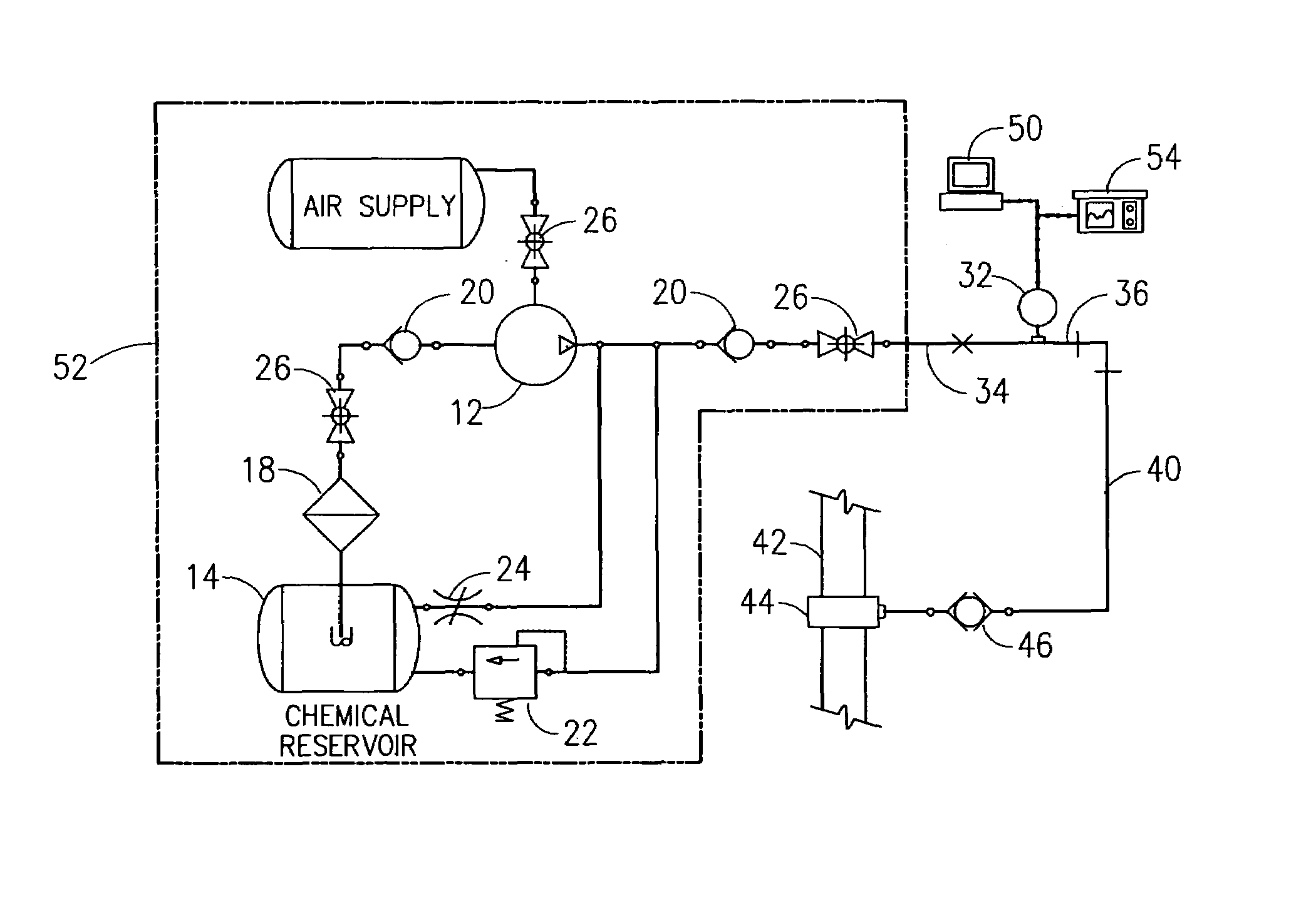
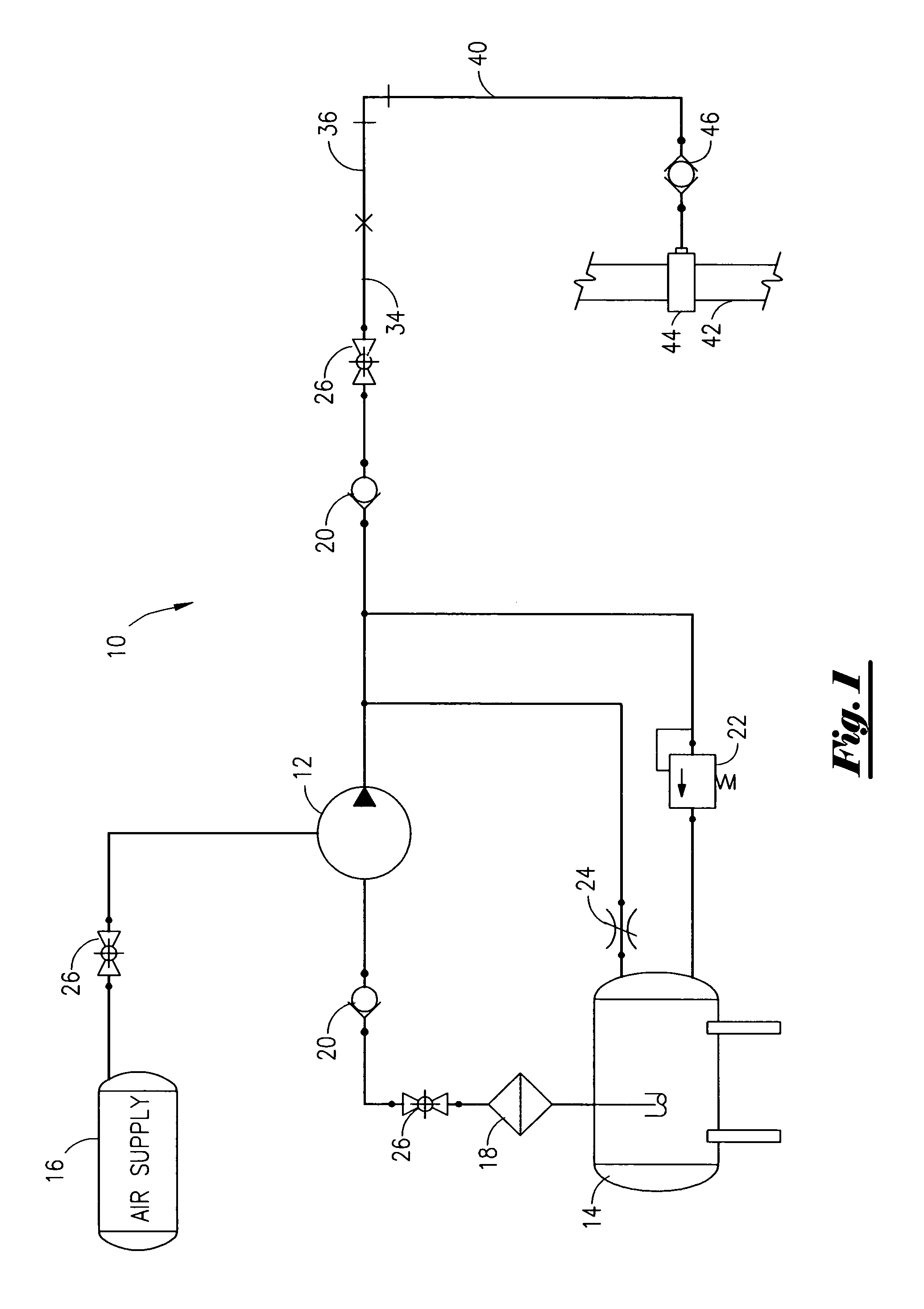
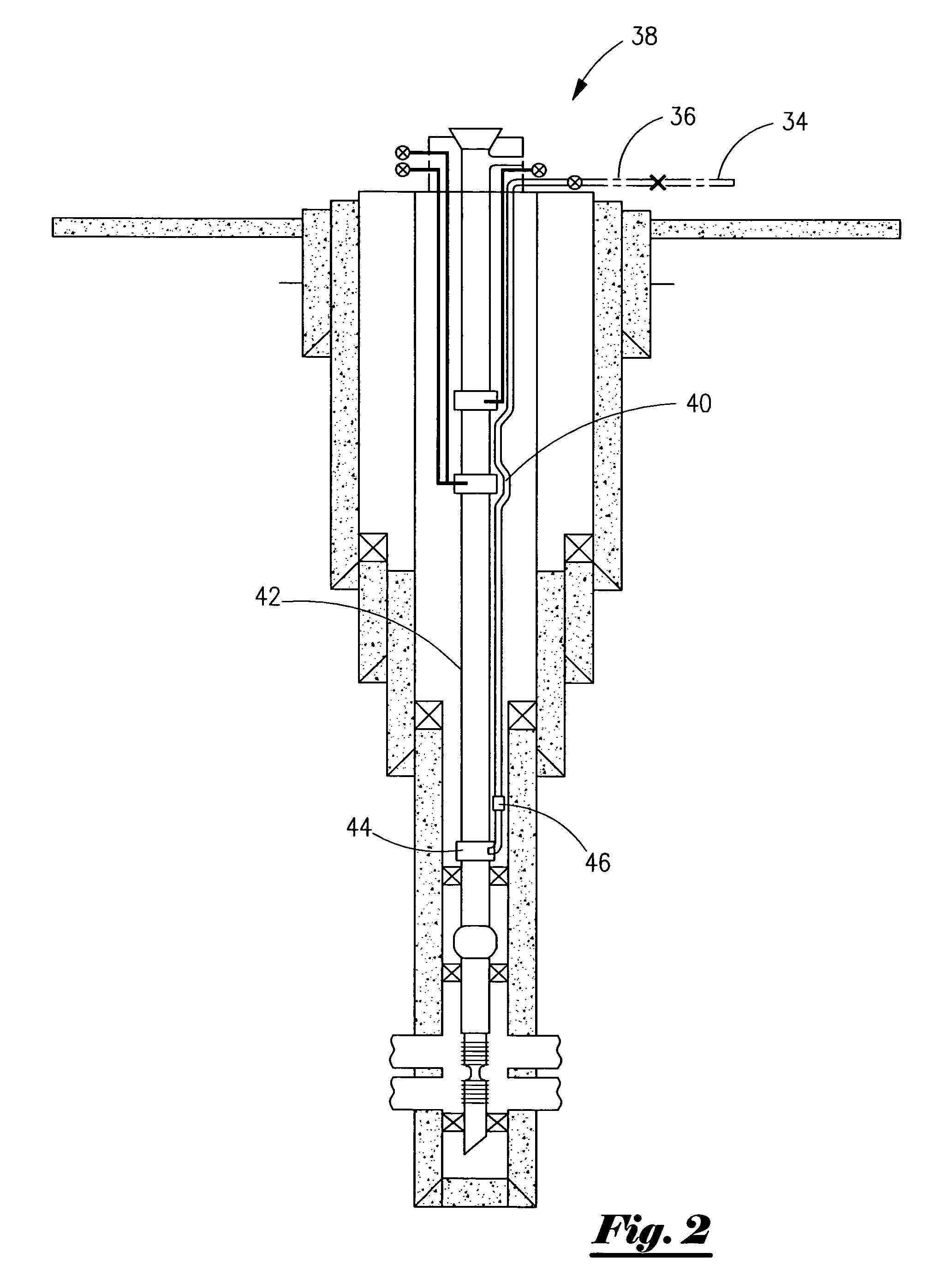
[0036]An improved, permanent down-hole pressure monitoring system is disclosed that utilizes a modified oil and gas well chemical injection system. A basic chemical injection system or chemical pressure monitoring system (CPMS) 10, as illustrated in FIG. 1, includes a relatively low volume, high pressure injection pump 12, a chemical reservoir 14, an air supply 16, and the usual suction and discharge filters 18, check valves 20, safety valve 22, needle valve 24, and cutoff valves 26. Chemicals are discharged from the pump 12 through the discharge line 34 making external connection 36 with a chemical umbilical line leading to the wellhead 38. As seen in FIG. 2, a capillary tube 40 extending externally along the production casing 42 terminates at an injection port 44 near the bottom of the well formation, as shown in FIG. 1. Fluid flowing upwards through the production casing 42 is prevented from entering the chemical injection capillary tube by a down-hole double check or balance val...


PUM


Abstract

A non-electric down-hole formation pressure monitoring system utilizing a typical down-hole chemical injection system for pressure data acquisition used with surface computer integration to produce an accurate picture of formation pressure variations utilizing pressure differentials across a pressure balanced valve located adjacent the chemical injection orifice. Computer controlled manipulation of the injection pump pressure maintains a constant differential pressure across the pressure balance valve thus tracking the well formation pressure deviations. The surface computer monitors pump noise, plumbing noise due to vibration, etc., temperature, and fluid and / or gas coefficients, and compensates for any adverse effects that may affect the accuracy of the formation pressures. Down-hole pressure monitoring is achieved in chemical injection or dedicated pressure-monitoring mode with only minor surface adaptations to the well chemical injection pump skid.

Description

FIELD OF THE INVENTION[0001]This is a Continuation-In-Part application relying on applicant's previously filed non-provisional application Ser. No. 10 / 294,319 filed Nov. 13, 2002, now abandoned and its provisional application No. 60 / 338,130 filed Nov. 13, 2001, under 35 USC 120.[0002]This invention relates generally to a method and apparatus for combining the monitoring of down-hole pressures in oil and gas well operations with chemical injection operations and more particularly to the utilization of a modified chemical injection system for injecting chemicals remotely into oil and gas wells while computing and accurately recording production tubing pressures at the bottom of the well, continuously, in real time.GENERAL BACKGROUND[0003]Bottom-hole pressure measuring and continuous monitoring in particular are invaluable in the management of oil and gas wells for fiscal projections, production exploitation, and the prevention of well or formation damage that can prematurely end the p...

Claims


Application Information

Patent Timeline
Patent Type & Authority Patents(United States)
IPC IPC(8): E21B47/06
CPCE21B47/06
Inventor FIRMIN, CULLY
Owner BAKER HUGHES INC
Why Eureka
Try Eureka