Light-emitting element driving apparatus, control method of the same, optical encoder, and camera
a technology of light-emitting elements and driving apparatus, which is applied in the direction of mountings, instruments, and converting sensor outputs, etc., can solve problems such as difficulty in performing control corresponding to characteristics
- Summary
- Abstract
- Description
- Claims
- Application Information
AI Technical Summary
Benefits of technology
Problems solved by technology
Method used
Image

Examples
first embodiment
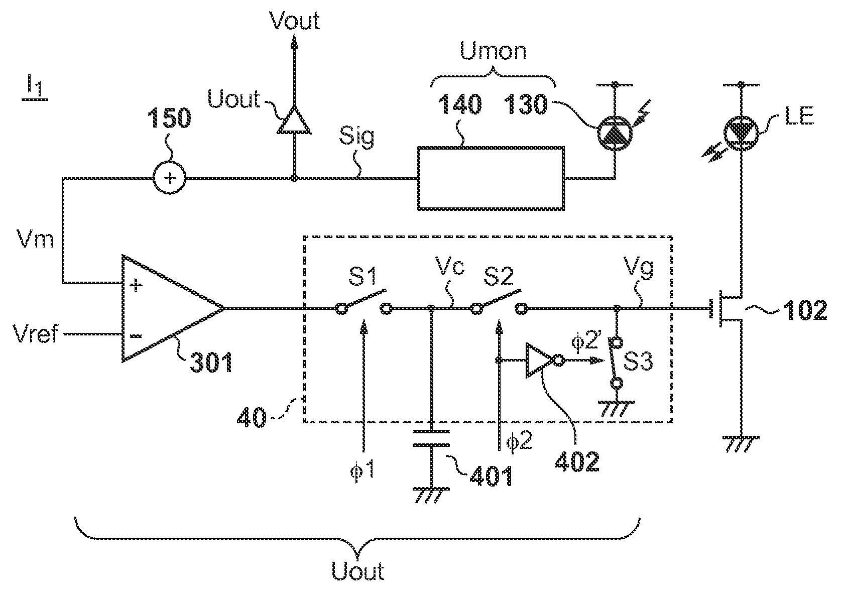
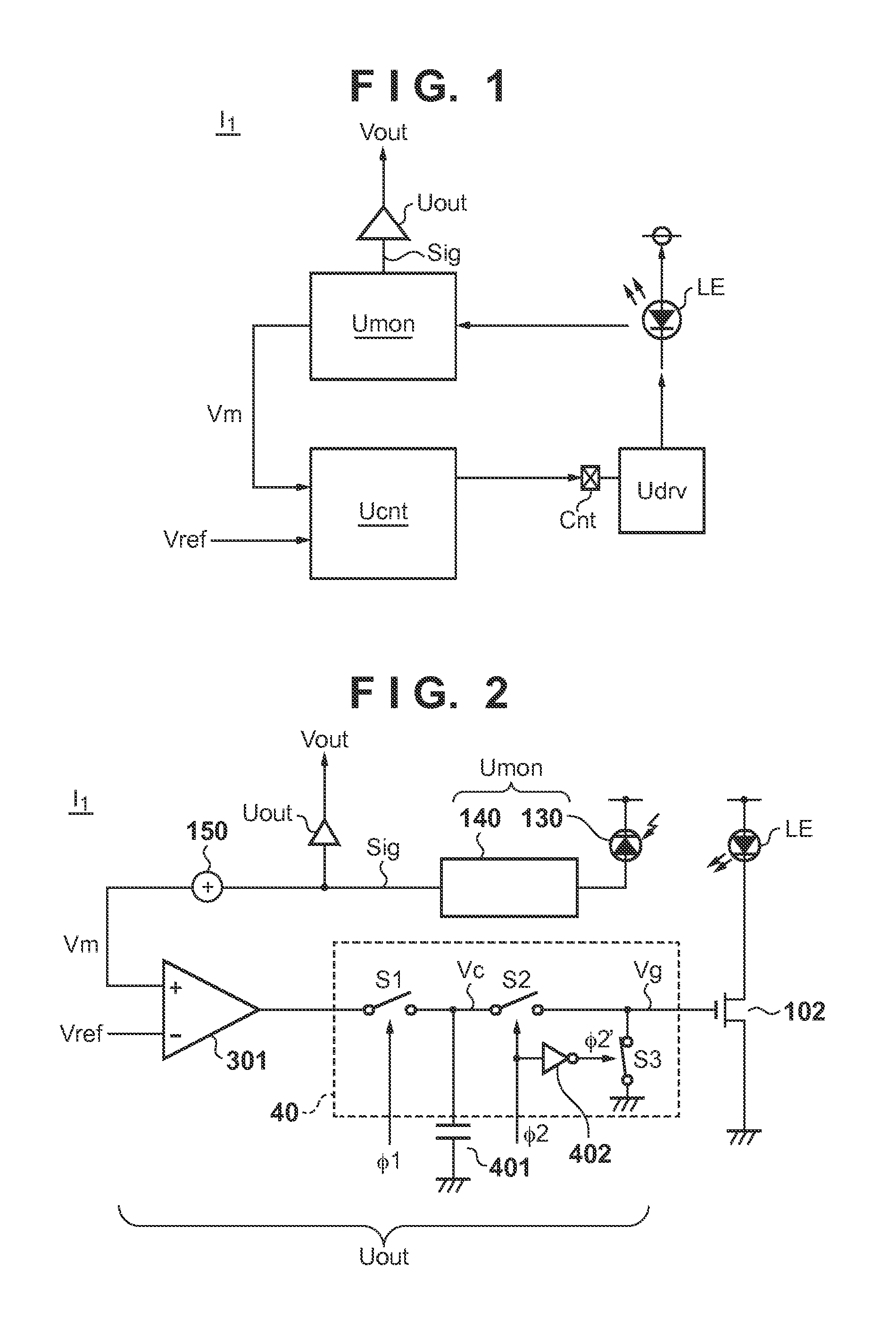
[0024]A light-emitting element driving apparatus I1 of the first embodiment will be explained with reference to FIGS. 1 and 2. As exemplified in FIG. 1, the light-emitting element driving apparatus I1 includes a light-emitting element LE, driving unit Udrv, and controlling unit Ucnt. The driving unit Udrv has a control terminal cnt, and drives the light-emitting element LE in accordance with the potential of the control terminal cnt. The light-emitting element driving apparatus I1 can also include a monitor unit Umon for monitoring the emitted light amount of the light-emitting element LE. The light-emitting element driving apparatus I1 can further include a signal output unit Uout for outputting a signal Vout corresponding to a signal Sig output from the monitor unit Umon.
[0025]The signal output unit Uout can output the signal Vout as a first signal when the light-emitting element is in the non-emitting state, and output the signal Vout as a second signal when the light-emitting el...
second embodiment
[0046]A light-emitting element driving apparatus I2 of the second embodiment will be explained with reference to FIG. 4. A main difference of this embodiment from the first embodiment in which the voltage Vc is held by using the switch S1 is that a voltage Vc of a capacitor 401 is held by using a current source. FIG. 4 shows a differential amplifier 301, a current source 302 placed between the output terminal of the differential amplifier 301 and a power line, and a current source 303 placed between this output terminal and GND. The light-emitting element driving apparatus I2 can also include a current source 403 instead of the switch S1 of the first embodiment. A monitor unit Umon and signal output unit Uout are the same as those of the first embodiment, and hence are not shown in FIG. 4.
[0047]A control signal Φ2a, for example, switches a driving state and pause state of the current source 302. Also, a control signal Φ2b, for example, switches a driving state and pause state of the...
third embodiment
[0052]A light-emitting element driving apparatus I3 of the third embodiment will be explained with reference to FIG. 6. This embodiment differs from the first embodiment in that a voltage conversion circuit 410 (a second transfer unit) is used instead of the switch S2 (a first transfer unit). The voltage conversion circuit 410 can be controlled by control signals Φ1 and Φ2. The arrangement of this embodiment using the voltage conversion circuit 410 is advantageous when a voltage Vc is to be, for example, amplified or boosted without directly transferring the voltage Vc to the gate terminal.
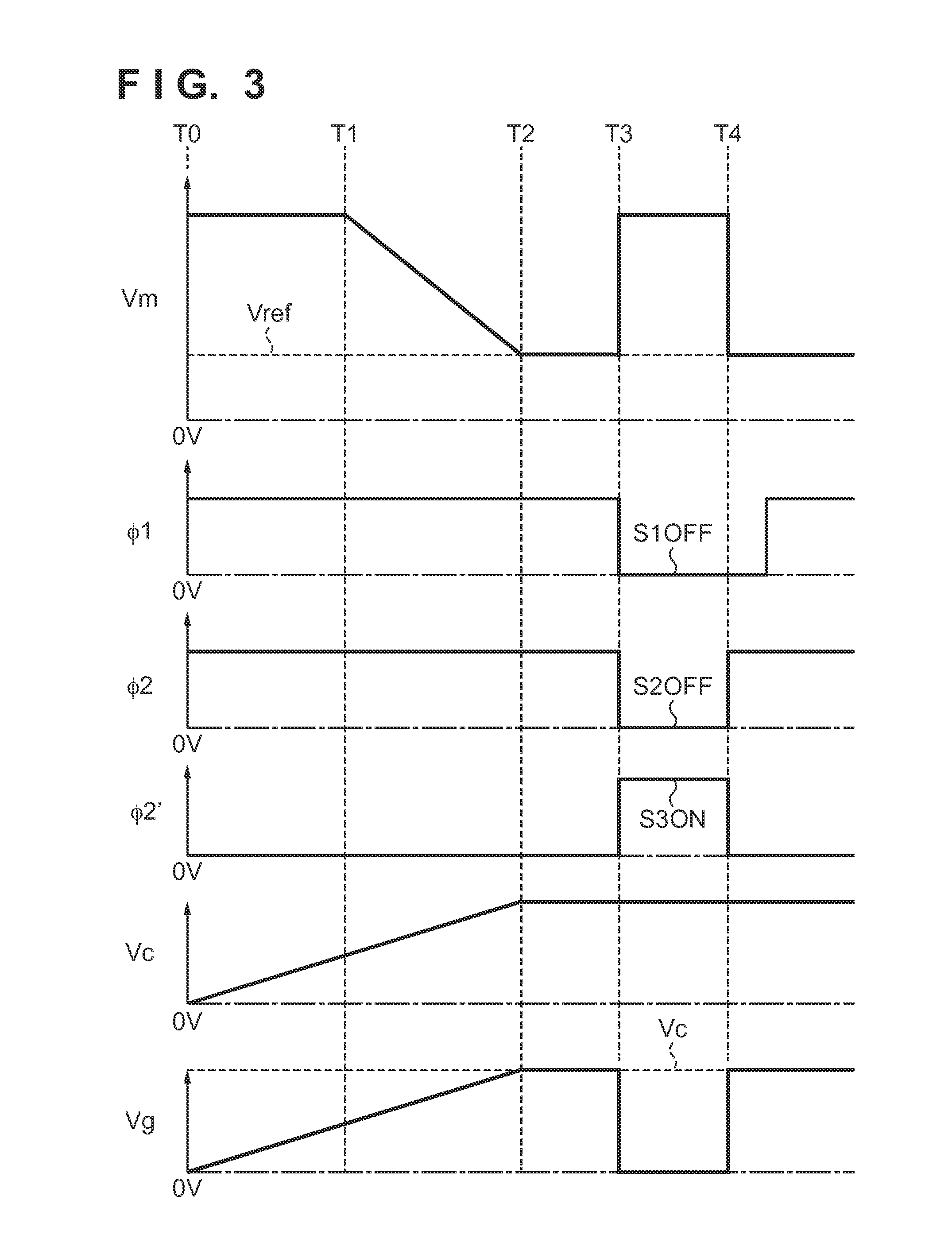
[0053]At times T0 to T3 in the sequence (FIG. 3) described in the first embodiment, the voltage conversion circuit 410 outputs a voltage corresponding to the input voltage Vc, in response to the change of the control signal Φ2 to High level. At times T3 and T4, the voltage conversion circuit 410 outputs HiZ (high impedance) in response to the change of the control signal Φ2 to Low level. Therefore...
PUM
 Abstract
Description
Claims
Application Information
 - R&D
- Intellectual Property
- Life Sciences
- Materials
- Tech Scout
- Unparalleled Data Quality
- Higher Quality Content
- 60% Fewer Hallucinations
Browse by: Latest US Patents, China's latest patents, Technical Efficacy Thesaurus, Application Domain, Technology Topic, Popular Technical Reports.
© 2025 PatSnap. All rights reserved.Legal|Privacy policy|Modern Slavery Act Transparency Statement|Sitemap|About US| Contact US: help@patsnap.com