Radio control device for target object to be controlled

a radio control device and target object technology, applied in the direction of television systems, electric controllers, instruments, etc., can solve the problem of difficulty in immediately selecting the model data corresponding to the target object, and achieve the effect of fewer errors, and less errors in selecting model data

Active Publication Date: 2015-06-23
FUTABA CORPORATION
View PDF4 Cites 1 Cited by
  • Summary
  • Abstract
  • Description
  • Claims
  • Application Information

AI Technical Summary

Benefits of technology

[0012]In view of the above, the present invention provides a radio control device with high convenience and performance, which requires no additional external device and is capable of storing model data and corresponding target objects in association therebetween and calling and setting model data corresponding to a desired target object with no mistake for immediate use.
[0018]If two or more target objects and corresponding model data are stored in the storage unit in association therebetween and model data used to control a particular one of the target objects are set in the radio target device, the user can select the particular target object based on the specific data stored in the storage unit, call the model data associated with the specific data corresponding to the selected target object, and set the called model data in the device for control of the target object. The operation of acquiring the target object specific data can be performed by only the radio control device, the association of the specific with the target object can be easily performed, and the model data corresponding to the target object to be controlled can be reliably called and set with no mistake.
[0019]In accordance with the aspect of the present invention, when the association of the target object specific data acquired by the camera module with the model data is performed, the specific data are visually displayed on the display unit so that the user can verify target objects with his / her eyes, thereby making few errors in the association or relationship. In this case, the user can manipulate the setting unit to call the model data corresponding to the target object from various model data pre-stored in the storage unit and associate the called target object model data with the specific data.
[0020]In addition, if two or more specific data and corresponding model data are stored in the storage unit in association therebetween and model data used to control a particular one of the target objects are set in the radio target device, the specific data stored in the storage unit are visually displayed on the display unit so that the user can verify the displayed specific data with his / her eyes and selects a desired target object. Accordingly, the model data corresponding to the target object to be controlled can be reliably called and set in the device with no mistake. In addition, the user can manipulate the setting unit to modify the called model data in time.
[0021]In accordance with the aspect of the present invention, a target object is specified by image data of target object. Accordingly, when the operation of association of the image data of the target object acquired by the camera module with the model data is performed and model data used to control a corresponding target object are set in the radio control device after the association of the image data with the model data is stored in the storage unit, an image of the corresponding target object is visually displayed on the display unit so that the user can verify and select a desired target object with its image, which may result in fewer mistakes in selecting model data.
[0022]In accordance with the aspect of the present invention, as the camera module reads the unique identification codes attached to the target objects, the radio control device can the identification data for specifying the target objects. When the operation of association of the identification data of the target object acquired by the camera module with the model data is performed and model data used to control a corresponding target object are set in the radio control device after the association of the identification data with the model data is stored in the storage unit, the identification data of the corresponding target object are visually displayed on the display unit so that the user can verify and select a desired target object, which may result in fewer mistakes in selecting model data.

Problems solved by technology

However, in the above conventional radio control device, there is a problem of complicated operation of associating any model data with a target object to be controlled and storing such association in the device.
Accordingly, if the user cannot remember the name or model number of the desired target object, it is difficult to immediately select the model data corresponding to the target object.
However, the above proposed radio control device requires a separate digital camera for acquiring image data of target objects.
As described above, the above proposed radio control device requires the digital camera and the personal computer additionally and has a problem of complicated operation of associating target object model data with a target object to be controlled.

Method used


Image

  • Radio control device for target object to be controlled
  • Radio control device for target object to be controlled
  • Radio control device for target object to be controlled

Examples


first embodiment

[0030]A radio control device in accordance with the present invention will now be described with reference to FIGS. 1 to 6G.

[0031]A configuration of the radio control device will be first described with reference to FIGS. 1 to 3.

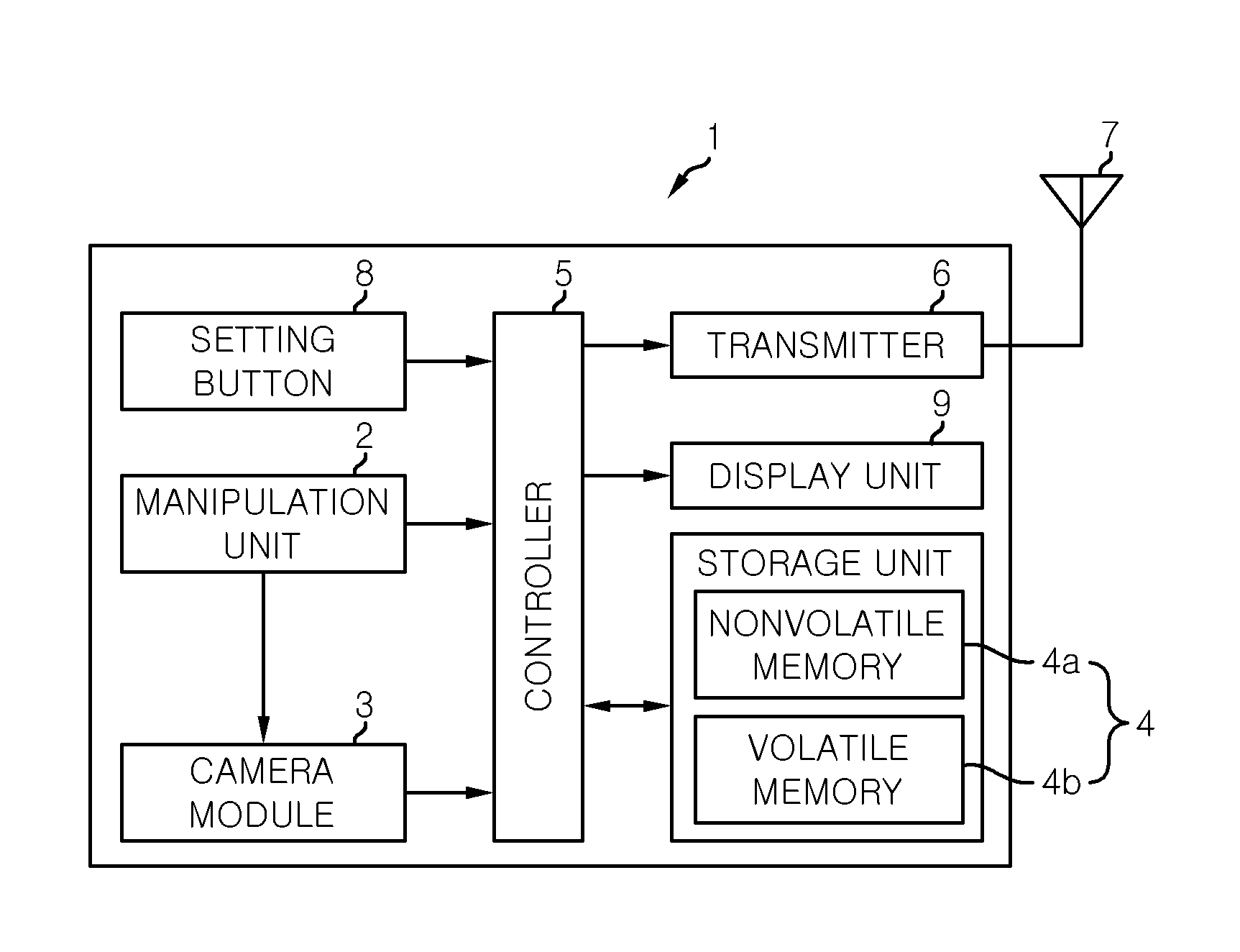
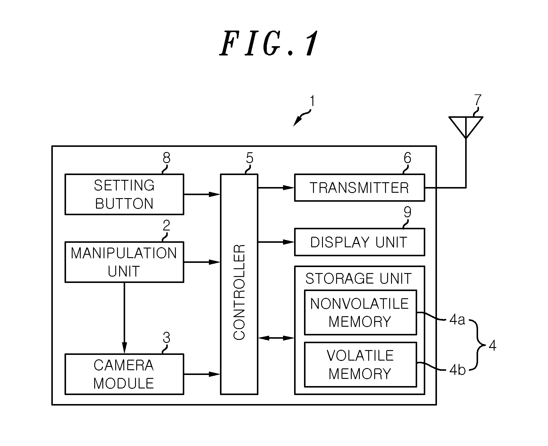
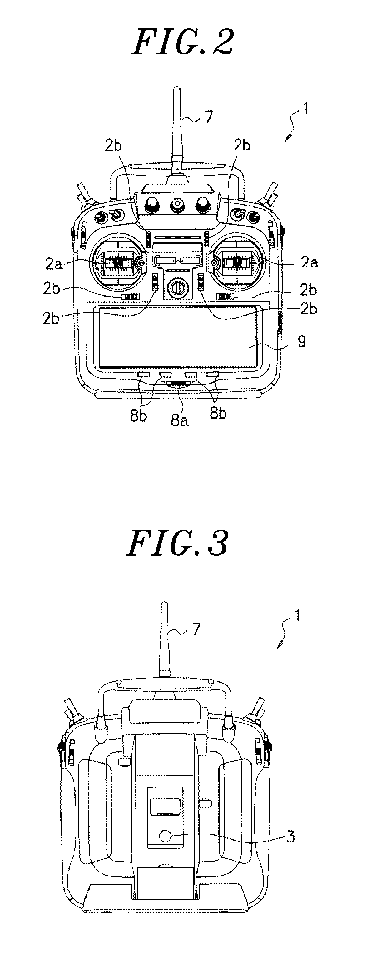
[0032]As shown in a functional block diagram of FIG. 1, radio control device 1 includes a manipulation unit 2 operated by a user who controls a target object (not shown) such as an airplane or the like. An example of the manipulation unit 2 may include a pair of left and right stick levers 2a as shown in FIG. 2, six trim switches 2b as shown in FIG. 2, other switches, buttons, levers and the like. The user may manipulate the manipulation unit 2 to control the target object by actuating a driving source such as an engine, and a servo motor and the like to drive a rudder and the like, equipped in the target object. The manipulation unit 2 may be a touch panel of a display unit 9 which will be described later.

[0033]As shown in FIG. 1, the radio control device 1...

second embodiment

[0067]Although, in the second embodiment, the identification data read from the identification codes printed on the labels are used as the specified data for the reading of the model data, image data of target objects acquired by the camera module 3 may be used as the identification codes. That is, features or characteristics of target objects may be extracted from the image data using an image recognition technique and may be made into codes which can be then used as the specified data for individual identification of the target objects.

[0068]In the second embodiment, when unique serial numbers of various radio control devices are coded and added to not only the labels but also model data stored in the radio control devices in association therebetween, a camera module 3 of a different radio control device cannot read identification codes of labels attached to different target objects for association with model data of the different target objects. This can prevent users from errone...


PUM


Abstract

A radio control device for one or more target objects to be controlled includes an manipulation unit, configured to control the target objects; a storage unit which stores model data corresponding to the target objects, the model data being used to control the target objects; a controller which uses the model data stored in the storage unit to control the target objects through manipulation of the manipulation unit; and a camera module which acquires specific data for specifying the target objects. The controller stores the specific data of the target objects acquired by the camera module and the model data of the target objects related to the specific data in the storage unit in association therebetween such that the specific data and the model data are callable from the storage unit.

Description

FIELD OF THE INVENTION[0001]The present invention relates to a radio control device for a target object to be controlled, and more particularly, to a user-friendly radio control device which is capable of storing model data in association with target objects to be controlled and controlling one selected from the target objects by calling and using model data corresponding to the selected target object without making errors.BACKGROUND OF THE INVENTION[0002]A radio control device for radio control of target objects to be controlled, such as airplanes, helicopters and the like, includes a manipulation unit such as a stick lever to control the target objects by actuate a driving source such as an engine or the like, or a servo motor to drive a key or the like. Depending on the kinds of target objects to be controlled (e.g., airplanes, gliders, helicopters and the like), roles (control targets) assigned to manipulation units and manipulation properties of manipulation units (e.g., relati...

Claims


Application Information

Patent Timeline
Patent Type & Authority Patents(United States)
IPC IPC(8): G05B11/01A63H30/04H04N7/18G08C17/02G05B17/02G06F3/038G06F3/01
CPCG05B17/02H04N7/183A63H30/04G08C17/02G06F3/038G06F3/017
Inventor YAMAMOTO, MICHIOISONO, TAKAHIROTOYOTOMI, KOTATANAKA, MASAHIRO
Owner FUTABA CORPORATION
Why Eureka
Try Eureka