
Filtering device for ponds and the like

a filtering device and pond technology, applied in the direction of filtration separation, separation process, liquid cleaning, etc., can solve the problems of system insufficient effectiveness, filter element rapid obstruction, device described in the patent is little practical in use, etc., and achieves effective filtering

Active Publication Date: 2015-06-30
SICCE SPA
View PDF9 Cites 0 Cited by
  • Summary
  • Abstract
  • Description
  • Claims
  • Application Information

AI Technical Summary

Benefits of technology

[0021]The present invention provides several relevant advantages. The main advantage lies in that device according to the present invention allow to provide an effective filtering without either requiring particular efforts to the user or imposing him or her to operate in excessively hard positions.

Problems solved by technology

Nevertheless, it is evident that the filtering element will be quickly obstructed by impurities and dirt in the pond.
Nevertheless, this system does not prove to be enough effective since a simple rinse of the filter does not suffice to a complete removal of the impurities present therein.
The device described in the patent proves to be little practical in use, since the actuating device allowing the surface to approach each other and press the filtering element, should be used in a particularly uncomfortable working position and it requires a remarkable physical force to perform the operation of compression.
Nevertheless, these filtering devices normally lay underground and, as a consequence, the back of the user operating on the handle is un-conveniently stressed, as the handle, in fact, will need to be pulled upward to press the filtering element.

Method used


Image

  • Filtering device for ponds and the like
  • Filtering device for ponds and the like
  • Filtering device for ponds and the like

Examples


Embodiment Construction

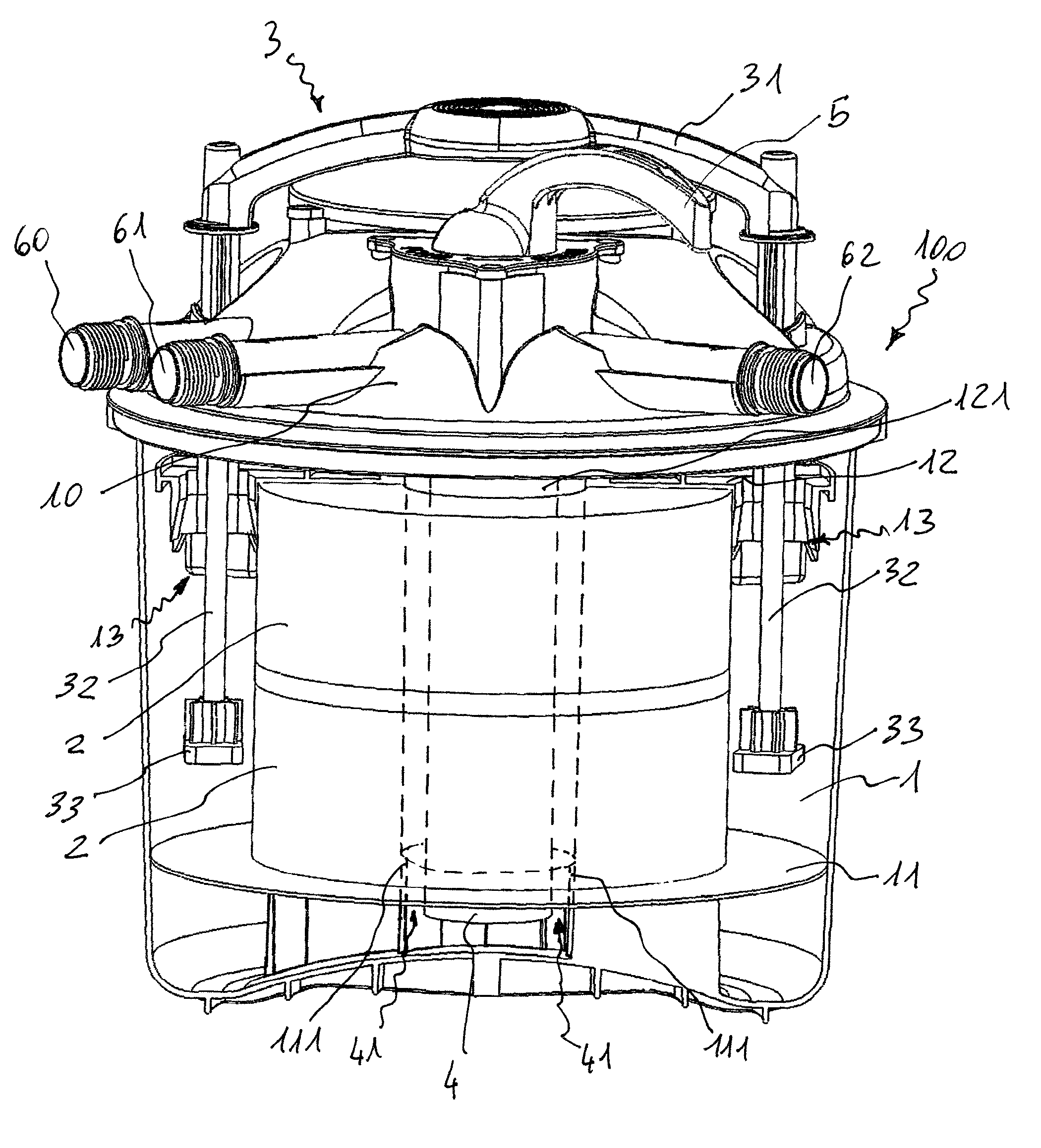
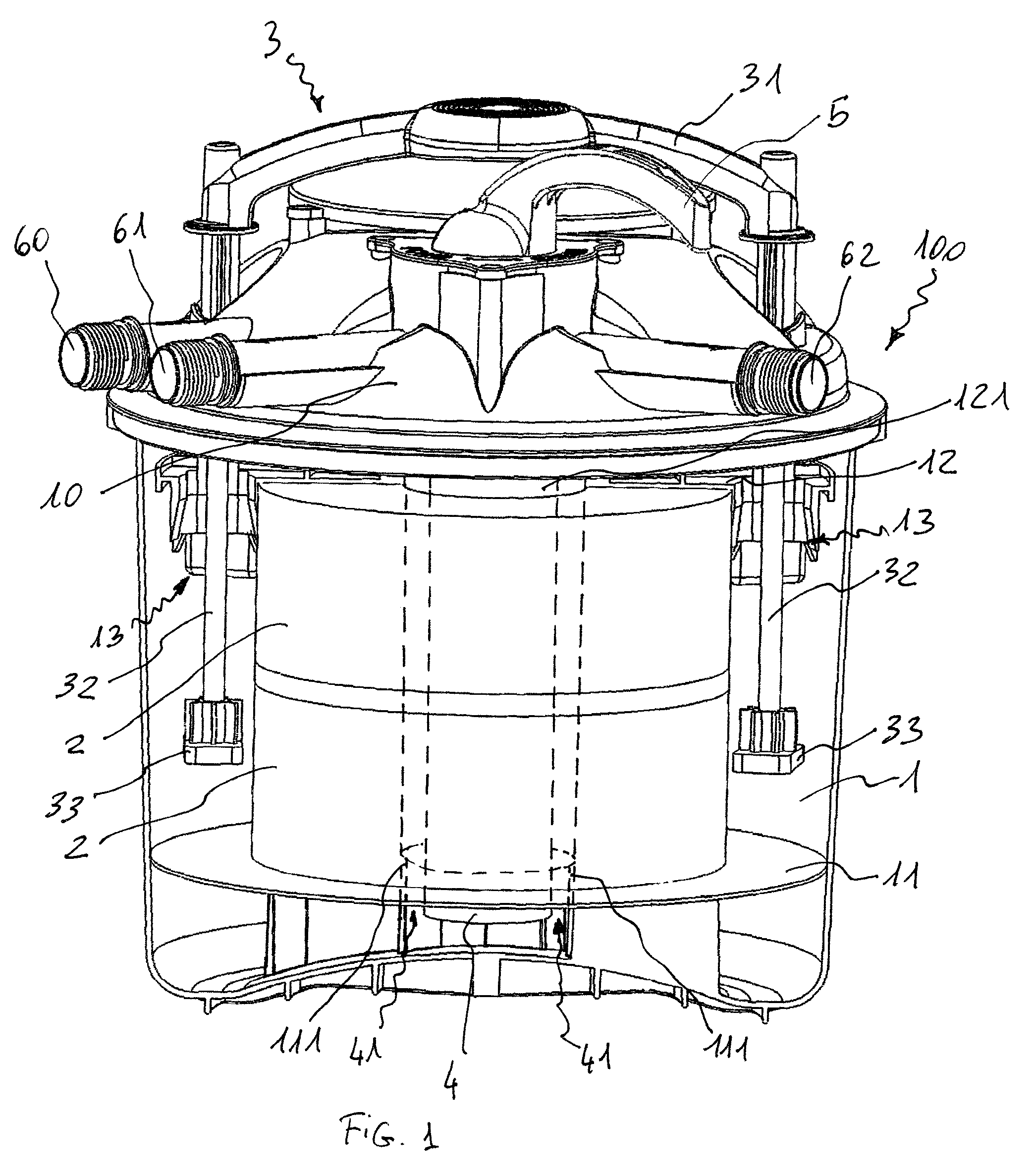
[0028]With reference initially to FIG. 1, a filtering device according to the present invention is on the whole shown with the reference 100.

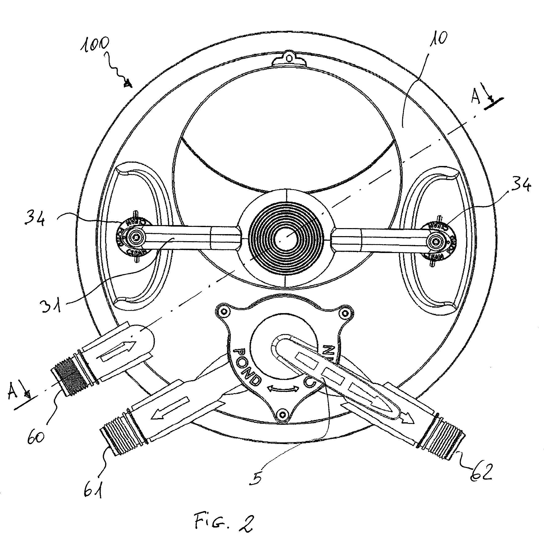
[0029]The device 100 comprises a container 1, provided with a closing lid 10. At the closing lid 10 there are provided an inlet 60 for the water coming from the pond, an outlet 61 for the delivery of the filtered water to the pond and an outlet 62 for delivery water during the rinsing step, which will be described in details in the following.

[0030]A filtering element 2 is placed inside the container 1, made, e.g., in spongy materials and, in particular, could be composed of a set of overlapped filtering elements 2.

[0031]The filtering element 2 is comprised between two supporting surfaces 11, 12 which could be brought the one near the other so as to compress the filtering element 2, as will be seen in the following.

[0032]For a better explanatory clearness, in the following it will be indicated as upper support surface 12 the surface closest to t...


PUM

PropertyMeasurementUnit
distanceaaaaaaaaaa
shapeaaaaaaaaaa

Abstract

A filtering device, allowing to provide an effective filtering without either requiring particular efforts to the user or imposing him or her to operate in excessively hard positions, comprises a filtering element comprised between a first and a second supporting surface, the distance between the supporting surfaces being adjustable, so as to compress the filtering element by moving the supporting surfaces the nearer the other, and actuating device apt to modify the distance of the supporting surfaces. The actuating device is selectively connectable to a surface of the supporting surfaces in a such way that the actuating device can alternatively move unrelated to motion of the surfaces so as to be placed in an operative configuration or move integral to the surface so as to modify the distance between the surfaces in order to compress the filtering element.

Description

CLAIM FOR PRIORITY[0001]This application is a U.S. National Stage Application of PCT / IB2009 / 053741 filed on Aug. 26, 2009, claiming priority to European Application No. 08 425 573.6 filed Aug. 26, 2008, the contents of both of which are incorporated herein by reference.TECHNICAL FIELD[0002]The present invention refers to a filtering device for ponds and the like.TECHNOLOGICAL BACKGROUND[0003]Artificial ponds placed in gardens require the use of a filtering device for keeping the water contained therein sufficiently clean.[0004]For this purpose, it is known to the art the use of filtering devices that intake water from the pond, filter it by a filtering element placed therein, and deliver it back inside the pond. Nevertheless, it is evident that the filtering element will be quickly obstructed by impurities and dirt in the pond. Accordingly, such filtering devices have systems for providing a periodical cleaning of the filtering element, so as to remove the impurities and the dirt th...

Claims


Application Information

Patent Timeline
Patent Type & Authority Patents(United States)
IPC IPC(8): C02F1/00A01K63/04B08B3/00B01D29/11
CPCA01K63/045B01D29/114B01D29/66B01D29/70B01D29/705
Inventor BARON, GIANCARLOPETTENON, PAOLO
Owner SICCE SPA
Learn More